Сотрудничество
ИСКУССТВО
КРАСОТА И ЗДОРОВЬЕ
РЕМЕСЛО
КУЛЬТУРА И ИСТОРИЯ
РАЗВЛЕЧЕНИЯ
ЭКОЛОГИЯ
ЕДА И НАПИТКИ
ОБРАТНАЯ ИНЖЕНЕРИЯ
НАУКИ
СПОРТ
ТЕХНОЛОГИИ
НОСИМЫЕ УСТРОЙСТВА
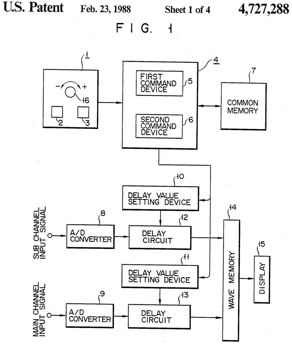


Oscilloscope: Two-Channel Digital, with a Delay per Channel and a Common Delay (Anritsu, US 4,727,288, 1988)
A two-channel digital oscilloscope. Each channel has its own converter and delay circuit. One knob, with a main and a sub button, sets the delays. The sub button shifts only the sub channel's wave, so you can line it up against the main one. The main button shifts both waves together and keeps the gap between them.
Result: a 2-channel digital oscilloscope that can move both traces along the time base without losing their phase difference.
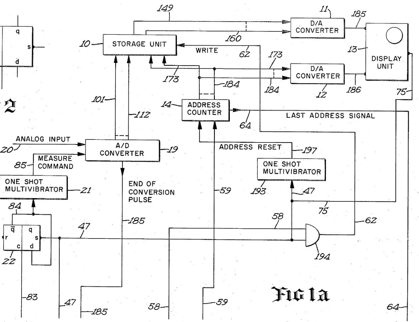
Source: K. Nakatsugawa et al. (Anritsu), US 4,727,288 (1988). Unknown: sample rate, bandwidth, memory size and the display. Picture: the patent drawing.
Эксперт
Unknown
Инструкции
1
1
Convert the two channels
Convert the two channels
Bring the main channel and the sub channel each to its own analog-to-digital converter. Ours: BNC sockets. Not given: the sample rate, the bandwidth.
Материалы для этого шага:
 Аналого-цифровой преобразователь2 main and sub converters
 Набор коаксиальных разъёмов (BNC / SO-239)1 input sockets
Необходимые инструменты:
 Паяльник
 Инструмент для снятия изоляции
2
2
Delay, store and display
Delay, store and display
Pass each channel's digital signal through its own delay circuit, whose delay is set by its own delay value setting device. Store both delayed signals in a wave memory and show them on the display. Ours: logic ICs for the delay circuits and setting devices, IC memory, and a CRT driven through D/A converters. Not given: how the delay circuits are built, the memory size, the display.
Материалы для этого шага:
 Набор логических микросхем1 delay circuits and setting devices
 Полупроводниковая память1 wave memory
 Цифро-аналоговый преобразователь2 display drive
 Электронно-лучевая трубка1 display
Необходимые инструменты:
ПаяльникИнструмент для снятия изоляции3
3
Build the delay panel and processor
Build the delay panel and processor
Make a delay operation panel with a main switch, a sub switch and one dial, with an encoder on the dial so each turn is read as a change in its output. Connect the panel to a microprocessor with a common memory that holds the sub channel's delay S in one area and the main channel's delay M in another. Mount it all in a case with its supply. Ours: push buttons, an aluminium case, a DC supply.
Материалы для этого шага:
 Кнопка2 main and sub switches
 Поворотный энкодер1 delay dial
 Микропроцессор1 command devicesПолупроводниковая память1 common memory
 Алюминиевый корпус1 case
Необходимые инструменты:
 Источник питания постоянного тока
 Сверлильный станокПаяльник
4
4
Program the two commands
Program the two commands
When the dial turns, read the encoder change e and which switch is held. Sub switch: add e to S, set the sum in the sub channel's setting device and store it back as the new S. Main switch: add e to both M and S, set M + e in the main channel's device and S + e in the sub channel's, and store both back. The main command so moves both channels by the same amount and keeps their relative delay.
Необходимые инструменты:
Паяльник5
5
Compare two waves
Compare two waves
Feed two signals in. Hold the sub switch and turn the dial to slide the sub channel's wave against the main one. Then hold the main switch and turn the dial: both waves move along the time base together, with the phase difference between them unchanged. Test it with a known signal.
Необходимые инструменты:
 Генератор сигналов
Материалы
10- 2 main and sub convertersЗаполнитель
- 1 input socketsЗаполнитель
- 1 delay circuits and setting devicesЗаполнитель
- 1 common memoryЗаполнитель
- 2 display driveЗаполнитель
- 1 displayЗаполнитель
- Заполнитель
- Заполнитель
- 1 command devicesЗаполнитель
- 1 caseЗаполнитель
По этому чертежу делают

Связанные чертежи
Эти чертежи делятся знаниями — техники, материалы или принципы
CC0 Общественное достояние
Этот чертёж выпущен под лицензией CC0. Вы можете свободно копировать, изменять, распространять и использовать эту работу в любых целях без запроса разрешения.
Поддержите мейкера, покупая товары через его чертёж, где он получает Комиссию мейкера установленную продавцами, или создайте новую итерацию этого чертежа и включите его как связь в свой чертёж для распределения дохода.