UBUHANZI
UBWIZA N'UBUZIMA
UBUKORIKORI
UMUCO N'AMATEKA
IMYIDAGADURO
IBIDUKIKIJE
IBIRIBWA N'IBINYOBWA
UBWUBATSI BUSUBIRA INYUMA
UBUMENYI
SIPORO
IKORANABUHANGA
IBYAMBARWA

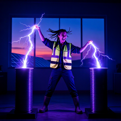

Knowing When To Stop: Finding the Peak That Says Full
The sealed cell of rung 1 solved the gas. It did not solve the question that comes straight after it: how does the charger know when to stop?
A sealed nickel cell will accept current indefinitely. Past full it simply turns that current into heat, quietly, until the seal or the separator gives up. It has no fuel gauge, and the only outward sign that it is full is a fall in terminal voltage of a few millivolts — perhaps one part in a hundred.
This rung builds the circuit that finds that signal, in the form David Pacholok patented in 1991: not by differentiating anything, but by racing the battery against a lagging copy of itself. Then it adds the two backstops that make the difference between a clever circuit and a charger you would leave running.
Hejuru
About 4 hours
Amabwiriza
1
1
Read the claim: three ways to stop, not one
Read the claim: three ways to stop, not one
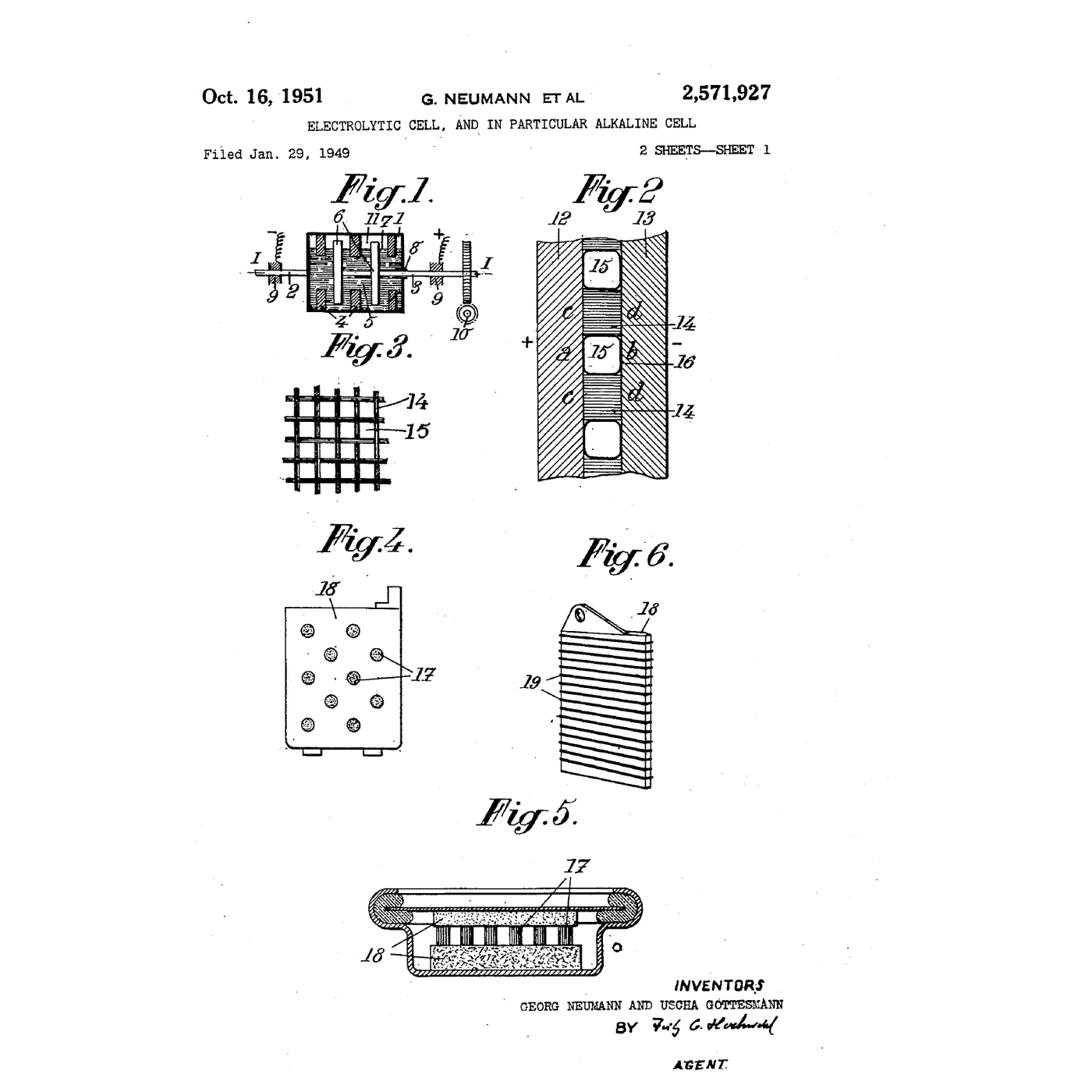
**US 5,196,780**, David R. Pacholok, filed **10 September 1991**, granted **23 March 1993**, expired. The figure on this page is its own sheet 1: FIG. 1 is the voltage-against-time curve with the peak marked, and FIG. 2 is the block diagram — FAST CHARGE and SLOW CHARGE blocks, the RC network into a comparator, and, along the bottom, **TH** and **TIMER**.
Write out the three terminations before you build anything, because the arrangement is the invention, not any one of them:
1. **−ΔV**, detected by a capacitor charged through a resistor from the battery terminal. The capacitor lags. When it *overtakes* the battery voltage, the battery must have turned over. No differentiator, no noise problem.
2. **A timer**, about eighteen minutes on fast charge. If the voltage signal never arrives, the charge still ends.
3. **A thermostat**, set between **40 °C and 60 °C**, on the cells themselves. If they get hot for any reason at all, the charge ends.
Then note what happens after termination: the circuit does not switch off, it drops to a **slow charge** that replaces self-discharge without overcharging. A charger that simply stops leaves you with a pack that is flat again by Thursday.
Sources for this one are clean and the number is verified. Where a later rung says a number could not be pinned, that is a statement about that rung, not a habit.
2
2
See the peak on a real cell before you try to detect it
See the peak on a real cell before you try to detect it
You cannot sensibly build a detector for a signal you have never seen. Log the signal first.
Put one discharged NiMH cell in a holder. Set the bench supply to constant current at **1C** — 2 A for a 2,000 mAh cell — with the voltage limit at 1.8 V so a bad connection cannot produce a surprise. Tape the thermocouple to the can.
Log terminal voltage to **four digits** and can temperature every minute. Four digits is not fussiness: the whole signal you are looking for is about 10 mV, so a three-digit meter reading 1.48 V cannot see it at all.
Expect, over roughly an hour:
- a quick rise in the first minutes as the cell polarises;
- a long, slowly-rising middle;
- a **peak**, then a fall of the order of 5–15 mV for a single cell;
- **temperature climbing sharply** from about the same moment.
Stop at the peak, or at 45 °C, whichever comes first. Mark on your log where the peak was and how many millivolts the fall was. That is the number your circuit has to resolve, and in a twelve-cell pack it is twelve times larger, which is why −ΔV termination works far better on a pack than on a single cell.
Ibikoresho by'iyi ntambwe:
 Bateri ya nikeli-hidiride y'icyuma1 igice
Ibikoresho bikenewe:
 Isoko ry'Amashanyarazi ryo ku Meza
 Multimeter ya dijitali — ibipimo byihitamo, RMS nyayo
 Ikipima ubushyuhe cy'ubwoko bwa K gifite modile ya MAX6675
 Igifata bateri
 Insinga z'Ibizamini Zifite Ibifatanyo
 Isaha yo Guhagarika
 Igitabo cya laboratwari (gifite kopi)
 Amadarubindi Asobanutse yo Kwirinda
3
3
Build the lagging copy
Build the lagging copy
Now build Pacholok's detector on the breadboard. It is four parts.
1. **The RC.** A resistor from the battery terminal into a capacitor to ground. Pick R and C so that R×C is the time constant you chose in step 4 — 470 kΩ with 470 µF gives about 220 seconds, near four minutes. Use a film or a low-leakage electrolytic; a leaky capacitor is a second resistor you did not plan for and it will hold the copy down permanently.
2. **The comparator.** An LM393, battery voltage on one input and the capacitor on the other. Its output flips the moment the capacitor wins.
3. **A little hysteresis.** A high-value resistor from the output back to the non-inverting input, a megohm or so, so the output snaps over instead of chattering across the crossing. Without it you will trip repeatedly on millivolt noise.
4. **The switch.** The comparator output drives the gate of the logic-level MOSFET, which carries the charge current. Logic-level matters: an ordinary MOSFET will not turn fully on from a 5 V gate and will dissipate the difference as heat.
Test it without a battery first. Put the function generator on the input with a very slow triangle — a few minutes per cycle, one or two volts peak to peak — and check that the output flips shortly after each apex and not before. A signal generator that you can turn around at will is a far better test than a cell that turns over once an hour.
Then put your logged cell curve in front of it for real. Watch the capacitor voltage on one scope channel and the cell on the other; the crossing is visible and it is the whole point of the circuit.
Ibikoresho by'iyi ntambwe:
 Ikusanyirizo ry'Ibirwanya Amashanyarazi bya 1/4 W1 igice
 Agafuka k'ibibiko by'amashanyarazi1 igice
 Insinga yo guhuza1 igice
Ibikoresho bikenewe:
 Ikibaho cy'Ibizamini
 Umutwe w'insinga za Dupont (igabo-igore)
 Urunigi rwibumbye rwa mugereranya kabiri LM393
 MOSFET y'urwego rwa lojiki IRLZ44N
 Potensiyometero iringaniye ya kilo-ohm 10
 Osilosikopu ya Digitale
 Igikora Imirongo y'AmashanyaraziMultimeter ya dijitali — ibipimo byihitamo, RMS nyayo
 Ahantu ho Gushongesha
 Utwuma two gufata dufite impera zityaye
 Igikoresho cyo gukuramo igifuniko cy'insinga
4
4
Choosing the time constant, and why three detectors beat one
Choosing the time constant, and why three detectors beat one
Gupakira ikaye ya Jupyter…
5
5
Add the two backstops
Add the two backstops
A −ΔV detector on its own is a circuit that can fail silently, and the failure mode is a charge that never ends. Add the other two.
**The thermostat.** Use the pack's own thermistor if you have the TH pin from rung 3, or a 10 kΩ NTC taped to the cell. Put it in a divider with a fixed resistor and feed the junction into the second half of the LM393; set the reference with the potentiometer so the comparator trips at about **45 °C**. Calibrate it, do not assume it: warm the thermistor with the heat gun on its lowest setting while watching the infrared thermometer, and adjust until the trip lands where you want it. Wire this comparator's output so it can cut the MOSFET gate **regardless** of what the −ΔV half is saying.
**The timer.** The 555 in monostable mode with a long RC gives you Pacholok's eighteen minutes. Work R and C out for your own charge rate rather than copying his: eighteen minutes is right for the rate his charger used, and a timer set for the wrong rate is worse than none because it will cut short every good charge.
Now test each one **alone**. Disconnect the −ΔV half and prove the thermostat stops the charge. Disconnect the thermostat and prove the timer does. A redundancy you have never tested individually is not redundancy, it is three circuits and a hope.
Finally, add the slow-charge path: a resistor that keeps a trickle flowing after termination, at something like C/40. Measure it with the meter and check it against the cell's own self-discharge rate.
Ibikoresho by'iyi ntambwe:
Ikusanyirizo ry'Ibirwanya Amashanyarazi bya 1/4 W1 igiceAgafuka k'ibibiko by'amashanyarazi1 igiceBateri ya nikeli-hidiride y'icyuma1 igiceIbikoresho bikenewe:
Ikibaho cy'IbizaminiUmutwe w'insinga za Dupont (igabo-igore)Urunigi rwibumbye rwa mugereranya kabiri LM393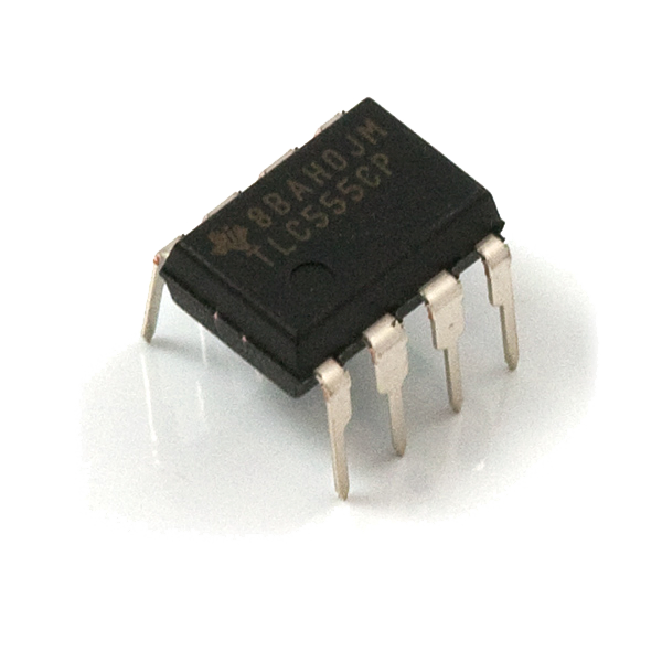 555 Timer
 Igikoresho cya thermistor za NTCPotensiyometero iringaniye ya kilo-ohm 10MOSFET y'urwego rwa lojiki IRLZ44N
 Imbunda y'umwuka ushyushye
 Igipima Ubushyuhe cya InifuraroujeMultimeter ya dijitali — ibipimo byihitamo, RMS nyayoOsilosikopu ya DigitaleAmadarubindi Asobanutse yo Kwirinda
6
6
History and context
History and context
**Attribution.** US 5,196,780, David R. Pacholok, filed 10 September 1991, granted 23 March 1993, expired. The drawing on this page is the patent's own.
**Why 1991 and not 1961.** The −ΔV effect was understood long before this patent; cell makers had been describing it in application notes for years. What was missing was a way to detect a few millivolts of *fall* on a signal riding on more than a volt, cheaply enough to put in a consumer charger, without a microcontroller. The RC-lag trick is the answer to the 'cheaply enough' part, and it is a genuinely elegant one — it replaces a differentiator, which amplifies noise, with a delay, which suppresses it.
**What it changed for makers.** Before reliable termination, the safe charge rate was C/10 overnight, because the recombination cycle could absorb that indefinitely. After it, fast charging became ordinary, and a fast charger is what makes a two-pack workflow work: one in the tool, one on the charger, and no waiting. Rung 3's pack and this rung's charger only make sense together.
**Honest limits.** −ΔV is a nickel-chemistry signal and it does not exist in lithium-ion, whose voltage only ever rises; lithium cells terminate on constant-current to constant-voltage and then on falling current, a different method entirely. −ΔV also gets harder as a pack ages, because the peak flattens, and it is nearly unusable on a single cell for the reason step 2 gives. And the whole scheme is built on the assumption that the cells in a pack reach full together — which, as rung 7 shows, they do not.
Ibikoresho
4- Umwanya
- Umwanya
- Umwanya
- 1 igiceUmwanya
Ibikoresho bikenewe
22- 14 vendors sell this, none ship to you yetUmwanya
- Umwanya
- Igitabo cya laboratwari (gifite kopi)10% komisiyoUmwanya
- 1 vendor sell this, none ship to you yetUmwanya
- 1 vendor sell this, none ship to you yetUmwanya
- Umwanya
- 1 vendor sell this, none ship to you yetUmwanya
Blueprint zijyanye
Izi blueprint zisangira ubumenyi — uburyo, ibikoresho cyangwa amahame


CC0 Umurenge rusange
Iyi blueprint yasohowe munsi ya CC0. Ushobora gukoporora, guhindura, gukwirakwiza no gukoresha nta kwemererwa.
Shyigikira Umuremyi ugura ibicuruzwa binyuze muri Blueprint ye Komisiyo y'Umuremyi byashyizweho n'Abacuruzi, cyangwa kora verisiyo nshya y'iyi Blueprint ukayinjiza nk'isano muri Blueprint yawe kugira ngo musangire inyungu.