Ubufatanye
UBUHANZI
UBWIZA N'UBUZIMA
UBUKORIKORI
UMUCO N'AMATEKA
IMYIDAGADURO
IBIDUKIKIJE
IBIRIBWA N'IBINYOBWA
UBWUBATSI BUSUBIRA INYUMA
UBUMENYI
SIPORO
IKORANABUHANGA
IBYAMBARWA
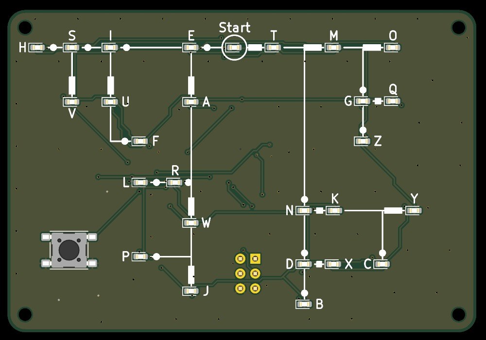
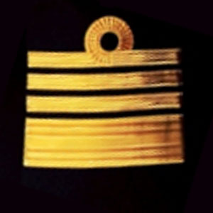

Pocket Morse Code Learning Board - v.1
A pocket board, 80 x 55 mm, that teaches you to read Morse code. Its front is Dave Nathanson's Morse decoding chart: from Start, dots run one way and dashes the other, and every letter sits where its dots and dashes lead. Here every letter has its own LED. Press the key short for a dot and long for a dash, and the LED of the letter you have reached lights; pause, and it blinks.
It runs on one CR2032 coin cell and sleeps between uses. The board was drawn with Youblob's Draw PCB, and its checks pass, but it has not been built yet.
Hejuru
About 1 day, plus board delivery
Amabwiriza
1
1
LED current and keying speed
LED current and keying speed
Gupakira ikaye ya Jupyter…
2
2
The code it decodes
The code it decodes
This board reads the International Morse code letters as ITU-R M.1677-1 gives them.
3
3
Read the chart
Read the chart
Dave Nathanson (KG6ZJO) drew his decoding chart in 2010: "Start with your finger at "Start Here". Then move your finger to track the Morse dots & dashes. You will arrive at the correct letter!" On this board the LEDs do the tracking. ITU-R M.1677-1: "A dash is equal to three dots."
4
4
The schematic
The schematic
ATmega328P on its internal 8 MHz clock, straight from the coin cell; 27 LEDs charlieplexed on PC0-PC5 through six 330 Ω resistors; the key on INT0; a 2x3 ISP footprint.
Ikireba KiCanvas kirapakirwa...
Ikireba cy'Umwuga cy'Igishushanyo cya PCB
5
5
The board
The board
Two layers, 80 x 55 mm. The chart, LEDs and key on the front; the chip, resistors, capacitors and cell holder on the back.
Ikireba KiCanvas kirapakirwa...
Ikireba cy'Umwuga cy'Igishushanyo cya PCB
6
6
Order the board
Order the board
Open the board in KiCad and plot Gerber and drill files (File > Fabrication Outputs). Order a two-layer board, 1.6 mm thick, from any board maker that takes Gerbers.
Ibikoresho by'iyi ntambwe:
 Ikibaho cy'umuzunguruko cyacapwe1 igice
Ibikoresho bikenewe:
 Mudasobwa Ifite Arduino IDE
7
7
Solder the parts
Solder the parts
Back first: paste and reflow U1, R1-R7, C1-C3 and the cell holder BT1 with hot air. Then the front: the 27 red LEDs D1-D27 with pad 1 (cathode) as the board's assembly drawing shows, and the key SW1. Leave J1 empty. Clean off the flux, then test each LED's direction with the meter's diode test.
Ibikoresho by'iyi ntambwe:
 Mikorokontorolewa ATmega328P1 igice
 LED ya shipu27 ibice
 Rezisitansi ya shipu7 ibice
 Kondenseri ya seramike ya shipu3 ibice
 Buto ikandwa1 igice
 Igifata bateri1 igice
 Pasita yo gukomatanya (idafite plombi)1 igice
 Urusinga rw'isudire1 igice
Ibikoresho bikenewe:
 Isitasiyo yo gusana n'umwuka ushyushye
 Icyuma cyo gusudira
 Utwuma two gufata dufite impera zityaye
 Umuti wo gusudira
 Indorerwamo Yagura
 Igipimo cy'amashanyarazi kinyuranye
 Alukoli ya isopropili 99 %
8
8
The firmware
The firmware
pocket_morse_decoder_az.ino: every timing is a named constant at the top of the sketch. Board in the Arduino IDE: Arduino Pro or Pro Mini, ATmega328P (3.3V, 8 MHz).
pocket_morse_decoder_az.inoarduino
9
9
Set the fuses and upload
Set the fuses and upload
Do not use Burn Bootloader: the Pro board setting expects a crystal, and this board has none. Hold an ISP programmer's 2x3 pins on J1 and set the internal 8 MHz clock: avrdude -c usbasp -p m328p -U lfuse:w:0xE2:m -U hfuse:w:0xD9:m -U efuse:w:0xFF:m. Then, in the Arduino IDE, use Sketch > Upload Using Programmer.
Ibikoresho bikenewe:
 Igikoresho cyandika porogaramu AVR ISPMudasobwa Ifite Arduino IDE
10
10
Print the back shell
Print the back shell
An open-front shell, 84.8 x 59.8 x 8.9 mm, with four standoffs for M2 screws, a slot to slide the cell out and a window under J1. PLA, 0.2 mm layers, 20 % infill, printed on its floor.
11
11
Fit the shell
Fit the shell
The shell leaves 5.0 mm for the back parts: measure your cell holder with a cell in it before you print. Check the holder's open side faces the board's left edge, where the shell's cell slot is. Slide in a CR2032 and screw the board into the shell with four M2 self-tapping screws.
Ibikoresho by'iyi ntambwe:
 Umugozi wa PLA1 igice
 Vise yikorera umurongo4 ibice
 Bateri y'igiceri CR20321 igice
Ibikoresho bikenewe:
 Imashini icapa 3D ikoresha umugozi (FDM)
 Kalipe ya Vernier
 Agatsiko ka tuneviza nyayo
12
12
Troubleshooting
Troubleshooting
Pocket Morse decoder troubleshooting.
Flow
Loading...
13
13
History and honest limits
History and honest limits
The chart is **Dave Nathanson**'s (KG6ZJO), drawn in 2010 and shared as copyleft; his post says it is a novel way to decode by following a path. The letter codes are ITU-R M.1677-1's. The board, sizes, parts and timings are ours, drawn with Youblob's Draw PCB: its ERC and DRC pass with no errors and every LED's wiring was checked against the firmware by script, but it has not been built, flashed or tested.
Ibikoresho
12- Umwanya
- 1 igiceUmwanya
- 27 ibiceUmwanya
- 7 ibiceUmwanya
- Umwanya
- Umwanya
- Umwanya
- Umwanya
- 1 igiceUmwanya
- 1 igiceUmwanya
- 4 ibiceUmwanya
- 1 igiceUmwanya
Ibikoresho bikenewe
12- Umwanya
- 2 vendors sell this, none ship to you yetUmwanya
- Umwanya
- Umwanya
- Umwanya
- Umwanya
- Umwanya
Dosiye z'igishushanyo
1Iki gishushanyo gikora
Blueprint zijyanye
Izi blueprint zisangira ubumenyi — uburyo, ibikoresho cyangwa amahame

CC0 Umurenge rusange
Iyi blueprint yasohowe munsi ya CC0. Ushobora gukoporora, guhindura, gukwirakwiza no gukoresha nta kwemererwa.
Shyigikira Umuremyi ugura ibicuruzwa binyuze muri Blueprint ye Komisiyo y'Umuremyi byashyizweho n'Abacuruzi, cyangwa kora verisiyo nshya y'iyi Blueprint ukayinjiza nk'isano muri Blueprint yawe kugira ngo musangire inyungu.