التعاون
فنون
الجمال والعناية
حِرَف
الثقافة والتاريخ
ترفيه
البيئة
الطعام والمشروبات
الهندسة العكسية
العلوم
رياضة
التقنية
الأجهزة القابلة للارتداء
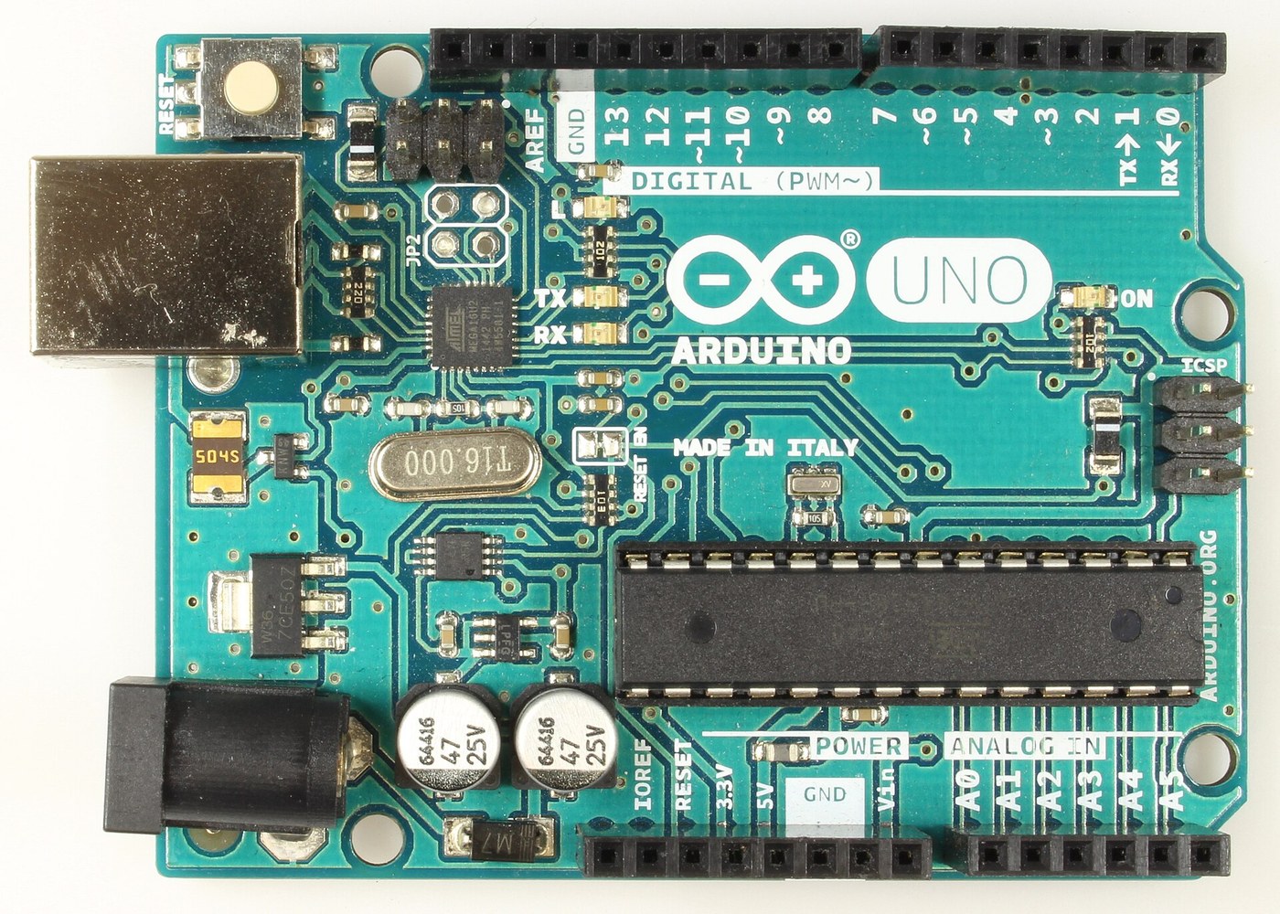


Arduino Uno R3: Assembled from Arduino's Open UNO-TH Rev3e Design Files and Flashed over ICSP
The Arduino Uno R3 is open hardware: Arduino publishes its schematic and board layout. This blueprint builds one from those files, part by part, then loads the firmware into its two processors.
Result: an Arduino Uno R3. An ATmega328P (16 MHz, 32 kB flash, 2 kB SRAM, 1 kB EEPROM) runs your programs; an ATmega16U2 turns USB into its serial link. It runs from USB (5.5 V at most) or 6-20 V at the DC jack.
Source: Arduino UNO-TH_Rev3e design files and the A000066 schematic and datasheet (Arduino, CC BY-SA). Unknown: how every bought part is made; no public source in hand says. The soldering method is ours. Picture: Wikimedia Commons.
متقدم
1 day
التعليمات
1
1
Get the bare board
Get the bare board
Have the two-layer board made to Arduino's UNO-TH_Rev3e board layout (the .brd file of the design files). Check it against the schematic before fitting anything.
المواد لهذه الخطوة:
 لوح دارة مطبوعة1 UNO-TH Rev3e layout
الأدوات المطلوبة:
 عدسة صائغ
2
2
Fit the small surface-mount parts
Fit the small surface-mount parts
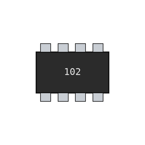
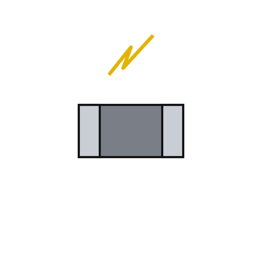
Solder the chip parts to their marked places: resistor arrays RN1 (10K), RN2 and RN4 (1K), RN3 (22R); R1, R2 (1M); capacitors C1, C2, C4-C7, C10 (100n), C3, C8 (1u), C9, C11 (22p); varistors Z1, Z2; ferrite bead L1; inductor L2 (10 uH); diodes D2, D3; LEDs ON (green), L, RX, TX (yellow). Ours: flux, tweezers and hot air or a fine iron, checked under a loupe.
المواد لهذه الخطوة:
 مصفوفة مقاومات شريحية4 RN1-RN4
 مقاومة شريحية2 1M
 مكثف خزفي شريحي11 7x100n, 2x1u, 2x22p
 مقاوم متغير بالجهد (شريحة)2 Z1, Z2
 خرزة فريت1 L1
 ملف حثي للتركيب السطحي1 L2
 ثنائي للتركيب السطحي2 D2, D3
 ثنائي باعث للضوء شريحي4 1 green, 3 yellow
 سلك لحام1 a little
الأدوات المطلوبة:
 مساعد صهر
 ملقط دقيق الطرفين
 محطة لحام بالهواء الساخن
 كاوية لحامعدسة صائغ
3
3
Fit the power and chip parts
Fit the power and chip parts
Solder the ATmega16U2 (U3), the 16 MHz resonator Y2 and crystal Y1, the 5 V regulator NCP1117 (U1) and 3.3 V regulator LP2985 (U2), the LMV358 op-amp (U5), the FDN340P transistor (T1), the M7 diode (D1), the 500 mA resettable fuse (F1) and the 47 uF capacitors PC1, PC2 with their polarity as marked.
المواد لهذه الخطوة:
 متحكم دقيق ATmega16U21 U3
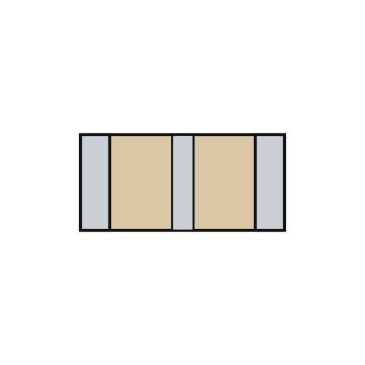 رنّان خزفي كهروإجهادي1 Y2
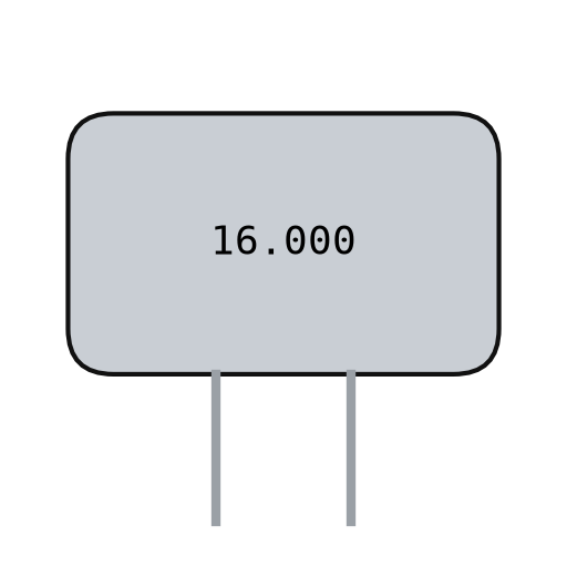 بلورة كوارتز1 Y1
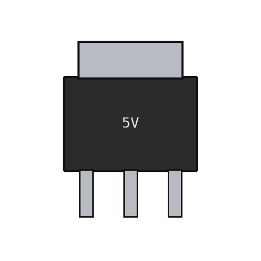 منظم جهد خطي2 U1 5 V, U2 3.3 V
 دارة مكبّر عمليات متكاملة1 U5 LMV358
 ترانزستور MOSFET بقناة P1 T1ثنائي للتركيب السطحي1 D1 M7
 صمام منصهر قابل لإعادة الضبط1 F1
 مكثف شريحي مستقطب2 PC1, PC2سلك لحام1 a little
الأدوات المطلوبة:
مساعد صهرملقط دقيق الطرفينمحطة لحام بالهواء الساخنكاوية لحامعدسة صائغ4
4
Fit the through-hole parts
Fit the through-hole parts
Solder the USB-B socket (X2), the DC jack (X1), the reset switch, the female headers (one 10-way, two 8-way, one 6-way) and the two 2x3 ICSP headers. Seat the ATmega328P in its place (ZU4).
المواد لهذه الخطوة:
 مقبس USB-B1 X2
 مقبس تغذية أسطواني1 X1
 زر ضغط1 RESET
 مشط تلامسات6 10x1, 2x 8x1, 6x1 female; 2x 3x2 ICSP
 متحكم دقيق ATmega328P1 ZU4سلك لحام1 as needed
الأدوات المطلوبة:
كاوية لحام5
5
Flash and check
Flash and check
Check with a meter that 5 V and GND are not shorted. Through the ICSP headers, load the USB-to-serial firmware into the ATmega16U2 and the bootloader into the ATmega328P. Plug in USB: the green ON LED lights, and the blink test in the next step flashes the L LED. Ours: an AVR ISP programmer and a multimeter.
المواد لهذه الخطوة:
 البرنامج الثابت لـ Arduino Uno1 download
الأدوات المطلوبة:
 جهاز قياس متعدد
 مبرمج AVR ISP
 كبل USB-B
6
6
The blink test
The blink test
blink_test.ino: the same check as Arduino's Blink example. Upload it over USB from the Arduino IDE with the board set to Arduino Uno; the L LED on pin 13 turns on for one second and off for one second, over and over. If it does, both processors, the USB link and the bootloader work.
blink_test.inocpp
الأدوات المطلوبة:
كبل USB-Bالمواد
24- 1 UNO-TH Rev3e layoutعنصر نائب
- 4 RN1-RN4عنصر نائب
- 2 1Mعنصر نائب
- 11 7x100n, 2x1u, 2x22pعنصر نائب
- 2 Z1, Z2عنصر نائب
- 1 L1عنصر نائب
- عنصر نائب
- 1 D1 M7عنصر نائب
- 4 1 green, 3 yellowعنصر نائب
- 1 as neededعنصر نائب
- عنصر نائب
- عنصر نائب
- 1 Y1عنصر نائب
- 2 U1 5 V, U2 3.3 Vعنصر نائب
- 1 U5 LMV358عنصر نائب
- عنصر نائب
- عنصر نائب
- 2 PC1, PC2عنصر نائب
- 1 X2عنصر نائب
- عنصر نائب
- عنصر نائب
- عنصر نائب
- عنصر نائب
- 1 downloadعنصر نائب
الأدوات المطلوبة
8- عنصر نائب
- عنصر نائب
- عنصر نائب
- عنصر نائب
- 2 vendors sell this, none ship to you yetعنصر نائب
- عنصر نائب
- عنصر نائب
- 1 vendor sell this, none ship to you yetعنصر نائب
هذا المخطط يصنع
المخططات ذات الصلة
هذه المخططات تشارك المعرفة مع هذا — التقنيات والمواد والمبادئ
CC0 ملكية عامة
هذا المخطط مُصدر بموجب CC0. يحق لك نسخه وتعديله وتوزيعه واستخدامه لأي غرض، دون طلب إذن.
ادعم الصانع بشراء منتجات عبر مخططه حيث يكسب عمولة الصانع يحددها البائعون، أو أنشئ نسخة جديدة من هذا المخطط وضمّنه كرابط في مخططك لمشاركة الإيرادات.