فنون
الجمال والعناية
حِرَف
الثقافة والتاريخ
ترفيه
البيئة
الطعام والمشروبات
الهندسة العكسية
العلوم
رياضة
التقنية
الأجهزة القابلة للارتداء
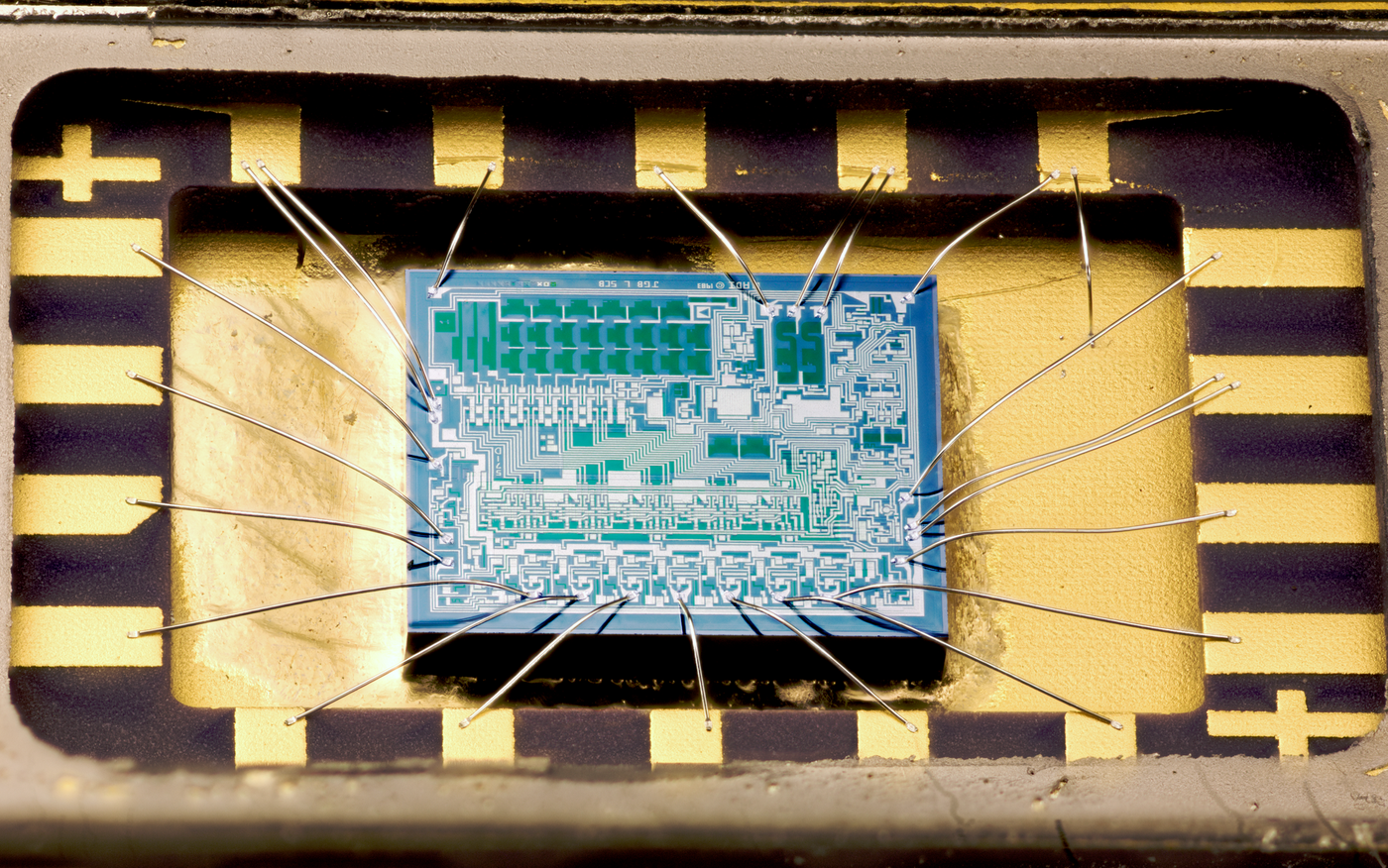


Die Attach
Sticking a chip to a metal paddle sounds like the least interesting step in assembly. It is the one that most often decides how long the part lives, and the reason is a mismatch nobody can avoid.
Silicon expands by about 2.6 parts per million per degree. Copper expands by 17. Heat a die bonded to a copper paddle by a hundred degrees and the copper tries to grow six and a half times as much as the silicon it is holding — and silicon is brittle, so it does not negotiate.
Every power cycle of every device is one repetition of that argument. The die attach layer sits between the two and absorbs the difference, and everything it must do pulls against something else it must do.
It must CONDUCT HEAT, because the die attach is in series with the only thermal path out of the chip, and a thermal resistance there raises the junction temperature of everything above it.
It must be COMPLIANT, to absorb the expansion mismatch without cracking the die or itself.
It must be STRONG, because it holds the die while it is wire bonded, moulded and shipped.
And it must be VOID-FREE, because a void is a hole in the thermal path, and a hot spot over a void is where the die cracks.
There are two main answers and they are a sibling pair. EUTECTIC bonding melts a gold-silicon alloy at 363 degrees and produces a metallurgical joint with superb thermal conductivity and almost no compliance. EPOXY — silver-filled, cured at 150 to 175 degrees — is far more compliant, far cheaper and far cooler to apply, and conducts an order of magnitude worse.
High power and hermetic parts use eutectic. Almost everything else uses epoxy, and the reason is not that epoxy is better but that most chips do not need the thermal path and every chip needs the cost.
You will bond dies both ways, measure the thermal resistance of each, and X-ray them the only way a maker can: by taking them apart.
متوسط
5 hours
التعليمات
1
1
Bond dies both ways, and find the voids
Bond dies both ways, and find the voids
Use silicon offcuts, glass squares or ceramic tile pieces as dummy dies — 5 millimetres square. You are practising a mechanical and thermal process, and nothing electrical is required.
EPOXY ATTACH, the easy one. Silver-filled thermally conductive epoxy, dispensed as a single dot in the centre of the paddle, and the die pressed down onto it. The dot spreads outward from the middle and pushes air ahead of it to the edges.
DISPENSE A SINGLE CENTRE DOT, not a ring or a pattern of dots. This is the whole technique. A ring traps air in the middle with nowhere to go, and that trapped air becomes a void directly under the hottest part of the die. Do it wrong deliberately on one sample — dispense four dots at the corners — and compare later.
Press with a controlled force and a slight scrub. The scrub — a small circular motion of a few tenths of a millimetre — breaks the surface tension and helps wet the paddle. Cure per the epoxy's schedule, typically 150 degrees for an hour.
EUTECTIC ATTACH, the harder one and worth attempting. Gold-silicon eutectic melts at 363 degrees, which is below the melting point of either gold or silicon alone — that is what eutectic means, and it is why the pair was chosen. Use a gold-plated substrate, a real silicon die, a hotplate that reaches 400 degrees, and nitrogen or forming gas if you can manage it, because gold oxidises little but the silicon surface must stay clean.
Bring the assembly above 363, place the die, and SCRUB it — a firm circular motion of a fraction of a millimetre. The scrub is not optional here either: it breaks the native oxide on the silicon and lets the gold reach bare silicon, and without it nothing wets and nothing bonds. You will feel the moment it takes, as the die suddenly slides freely and then grips.
NOW FIND THE VOIDS. Industry uses scanning acoustic microscopy, which you do not have. You have two methods that work.
FOR GLASS DIES, look through them. Bond a glass square with epoxy and the voids are directly visible from above as bright patches where the epoxy did not wet. Photograph and measure the void percentage with image analysis — this is the single most useful thing in the whole step, and it is why glass is worth using for the first attempts even though it is not silicon.
FOR OPAQUE DIES, break the joint. Shear the die off sideways with a chisel against a backing block and examine both faces. A good joint leaves epoxy on both surfaces across the whole area — the failure is inside the adhesive, which is what you want. A void appears as a clean, shiny region with no adhesive on either face. A joint that peels cleanly off the paddle with all the epoxy on the die never wet the metal at all.
COUNT THE VOID AREA on both your good sample and the deliberately-bad four-dot one. The industrial limit is typically 10 to 15 percent total voiding with no single void larger than 10 percent of the area, and the reason for that second clause is the next step.
المواد لهذه الخطوة:
 إيبوكسي موصّل محشوّ بالفضّة1 قطعة
 مشط دبابيس مطلي بالذهب10 قطع
 شرائح مجهرية مع أغطية20 قطع
 رقاقة نحاس أصفر (لألسنة الآلات)2 قطع
 كحول إيزوبروبيلي 99 %500 millilitre
الأدوات المطلوبة:
 صفيحة تسخين بمحرّك مغناطيسي
 مجهر رقمي
 طقم ملاقط دقيقة
 ميزان حرارة بالأشعة تحت الحمراء
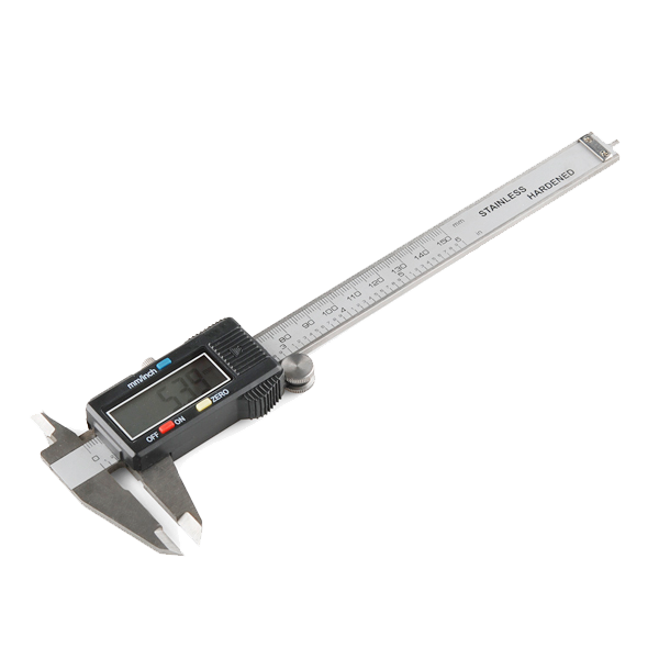 Digital Calipers - 152.4 mm
 قفّازات مقاومة للحرارة
2
2
Measure the thermal resistance you just built
Measure the thermal resistance you just built
The die attach is in series with the only path heat has out of the chip. Measure what yours costs.
MAKE A HEATED DIE. Bond a small resistor — a 10 ohm, 1 watt part, or a power resistor in a flat package — to the paddle using each attach method. It is your heat source and it stands in for the die's power dissipation.
INSTRUMENT IT. A thermocouple or DS18B20 bonded to the top of the resistor gives you the junction-side temperature. A second one on the paddle a few millimetres away gives you the other side. The difference across the joint is what you are measuring.
RUN IT. Apply a known power — measure voltage and current, do not assume — and let it settle for several minutes until the temperatures stop rising. Record both temperatures and the power.
Thermal resistance is the temperature difference divided by the power, in kelvin per watt. Do it at one watt, then two, then three, and confirm the resistance is roughly constant. If it rises with power you have something non-linear going on, most likely an air gap opening as things expand.
COMPARE YOUR TWO METHODS. Expect epoxy to be several times worse than eutectic. Silver-filled epoxy manages perhaps 2 to 6 watts per metre-kelvin; gold-silicon eutectic is around 25 to 30 times better than that. Across a thin layer the difference is real but not proportional to the bulk figures, because the layer is thin and the interfaces matter too — measuring it rather than calculating it is exactly the point.
NOW MEASURE THE BAD ONE. Take your deliberately voided four-dot sample and measure it the same way. The thermal resistance is markedly higher, and the effect is disproportionate to the void area, because heat does not spread sideways well in a thin layer — it goes straight down or not at all. A void directly under the heat source is far worse than the same void area spread around the edges.
That is why the specification limits the LARGEST single void rather than only the total, and now you have measured why.
THEN CYCLE IT. Power it on for two minutes and off for two minutes, repeatedly, for as many cycles as your patience allows, and re-measure the thermal resistance every fifty cycles. The expansion mismatch works the joint every cycle, and a joint that is going to delaminate does so progressively, showing up first as a slowly rising thermal resistance long before anything fails outright.
That rising number is the same kind of early warning as the flash erase time in blueprint five: the mechanism is completely different and the diagnostic shape is identical.
المواد لهذه الخطوة:
إيبوكسي موصّل محشوّ بالفضّة1 قطعة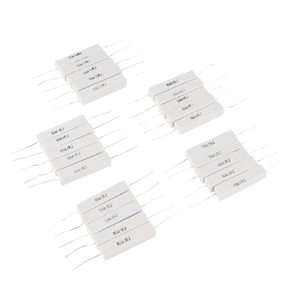 Power Resistor Kit - 10W (25 pack)1 طقم
 مجسّ حرارة DS18B204 قطعرقاقة نحاس أصفر (لألسنة الآلات)2 قطع
الأدوات المطلوبة:
 مزود قدرة مكتبي
 مقياس متعدد رقمي بدرجة مختبريةميزان حرارة بالأشعة تحت الحمراء
 لوحة تطوير ESP32
 ساعة إيقاف
3
3
Measure it properly, then cycle it until it drifts
Measure it properly, then cycle it until it drifts
The measurement described in the previous step is easy to take once and useless taken once. What matters is how the thermal resistance DRIFTS over many power cycles, and that needs hundreds of cycles at four minutes each — a loop, not a person with a notebook.
This sketch does three things. It measures thermal resistance properly: it drives the heater, waits for genuine thermal settling rather than a fixed guess, reads both temperatures and the actual electrical power, and divides.
IT MEASURES THE POWER RATHER THAN ASSUMING IT, which is the detail most people skip. A resistor's value changes as it heats, so computing power from the nominal resistance and the supply voltage is wrong by several percent at exactly the temperatures you care about. A shunt and an ADC cost nothing and remove the error.
Then it power-cycles — two minutes on, two minutes off — and re-measures every fifty cycles, logging the result.
WHAT TO WATCH IS THE TREND, NOT THE VALUE. A joint that is going to delaminate does so progressively: voids grow at the corners where the shear strain is highest, the conducting area shrinks, and the thermal resistance climbs steadily. The sketch flags a 30 percent rise, and when it does, stop and shear the die off immediately — a partially delaminated joint photographed at that moment shows exactly where the failure started, which a fully failed one does not.
Set the settling time honestly. Four minutes is not conservative; a small assembly genuinely takes that long to stop drifting, and a measurement taken at ninety seconds reads low and flatters the joint.
dieattach.inocpp
المواد لهذه الخطوة:
لوحة تطوير ESP321 قطعةمجسّ حرارة DS18B204 قطعPower Resistor Kit - 10W (25 pack)1 طقم ترانزستور MOSFET قناة N من طراز IRF540N2 قطع
 طقم مقاومات دقيقة1 طقم
الأدوات المطلوبة:
مزود قدرة مكتبيمقياس متعدد رقمي بدرجة مختبرية حاسوب مكتبيمجهر رقمي
4
4
Expansion mismatch, thermal path, and the choice
Expansion mismatch, thermal path, and the choice
جارٍ تحميل دفتر Jupyter…
الأدوات المطلوبة:
حاسوب مكتبيالمواد
10- عنصر نائب
- 10 قطععنصر نائب
- 20 قطععنصر نائب
- عنصر نائب
- 500 millilitreعنصر نائب
- Power Resistor Kit - 10W (25 pack)عمولة 10%1 طقم$5.66
- 4 قطععنصر نائب
- 1 قطعةعنصر نائب
- عنصر نائب
- 1 طقمعنصر نائب
الأدوات المطلوبة
11- عنصر نائب
- عنصر نائب
- عنصر نائب
- عنصر نائب
- Digital Calipers - 152.4 mmعمولة 10%$14.19
- عنصر نائب
- عنصر نائب
- عنصر نائب
- عنصر نائب
- عنصر نائب
- عنصر نائب
التكلفة الإجمالية المقدرة
ما اشتراه صانع المشروع. المواد التي تظهر بلا سعر تُشترى من حيث تجدها.
المخططات ذات الصلة
هذه المخططات تشارك المعرفة مع هذا — التقنيات والمواد والمبادئ


CC0 ملكية عامة
هذا المخطط مُصدر بموجب CC0. يحق لك نسخه وتعديله وتوزيعه واستخدامه لأي غرض، دون طلب إذن.
ادعم الصانع بشراء منتجات عبر مخططه حيث يكسب عمولة الصانع يحددها البائعون، أو أنشئ نسخة جديدة من هذا المخطط وضمّنه كرابط في مخططك لمشاركة الإيرادات.