التعاون
فنون
الجمال والعناية
حِرَف
الثقافة والتاريخ
ترفيه
البيئة
الطعام والمشروبات
الهندسة العكسية
العلوم
رياضة
التقنية
الأجهزة القابلة للارتداء

Pocket Morse Code Learning Board - v.3
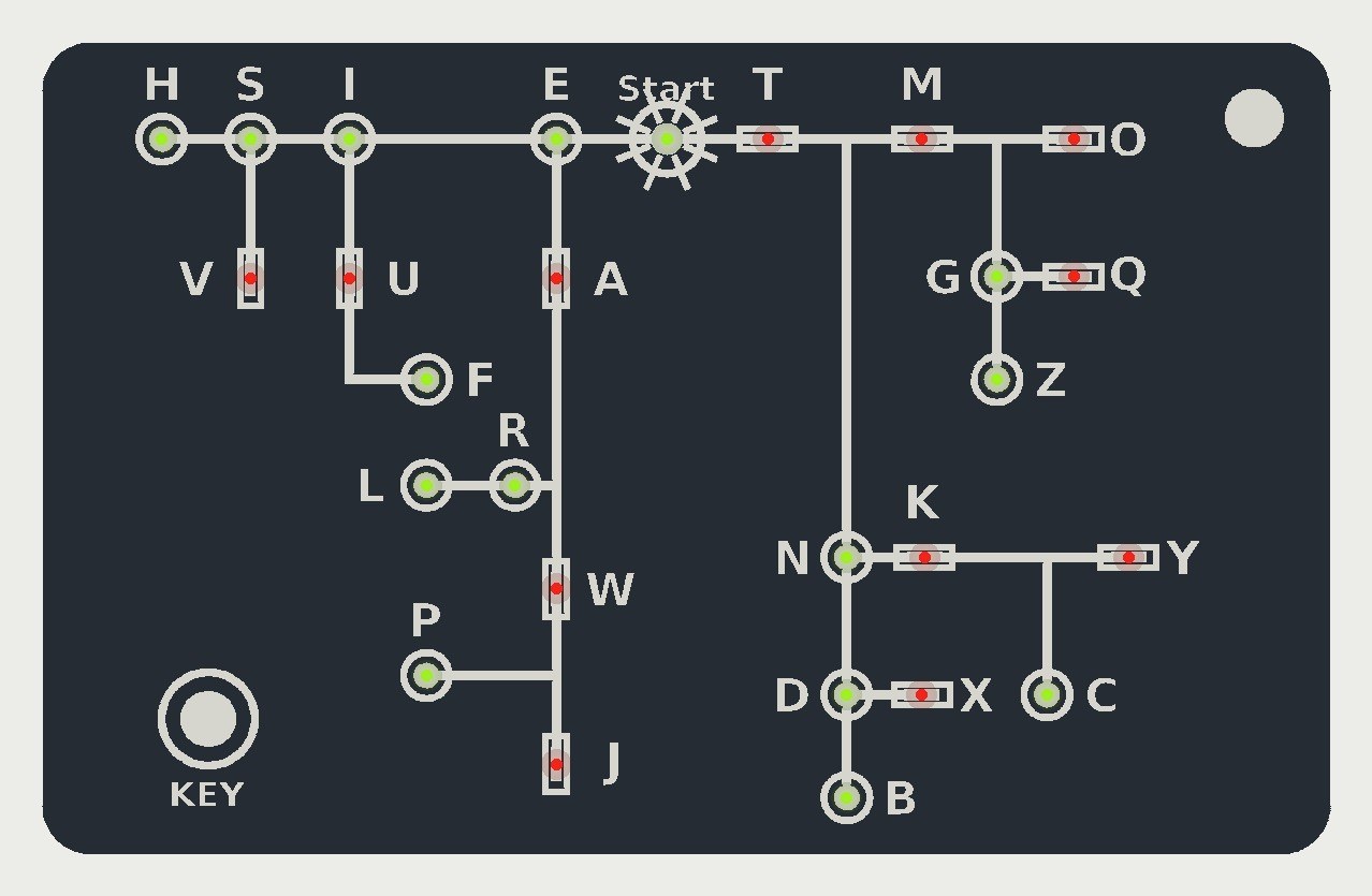
The pocket Morse decoder with no circuit board to order. A 3D-printed card the size of a bank card carries Dave Nathanson's decoding chart engraved in its face, with an SMD LED behind a window at every letter. Press the key short for a dot and long for a dash, and the letter you have reached lights.
Everything inside is hand-wired with enamelled copper wire to an Arduino Pro Mini, running on one CR2032 coin cell. The design has not been built yet.
متقدم
About 1 day, plus printing
التعليمات
1
1
LED current and keying speed
LED current and keying speed
جارٍ تحميل دفتر Jupyter…
2
2
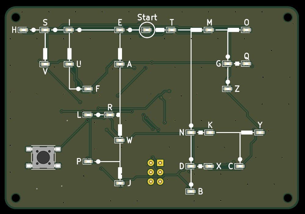
The same decoder on a circuit board
The same decoder on a circuit board
That version needs a board made to order. This one is printed and wired by hand.
3
3
Read the chart
Read the chart
Dave Nathanson (KG6ZJO) drew his decoding chart in 2010: "Start with your finger at "Start Here". Then move your finger to track the Morse dots & dashes. You will arrive at the correct letter!" On this card the LEDs do the tracking: yellow-green at the dots, red at the dashes.
4
4
Print the card body
Print the card body
The card, 85.6 x 54 x 7.5 mm, with the chart engraved 0.5 mm deep, a window and LED pocket at each letter, the key hole, four screw bosses and the key-ring hole. Print it face down on a smooth bed: PLA, 0.12 mm layers, no supports.
5
5
Print the lid
Print the lid
The 1.2 mm back lid with four countersunk screw holes and the credit and instructions engraved. PLA, 0.12 mm layers, engraved side down.
6
6
Fit the LEDs
Fit the LEDs
Press a 1206 LED into each pocket from the back, lens towards the window: yellow-green at the 14 dot rings and at Start, red at the 12 dash marks. Note each LED's cathode mark, then fix it with a tiny drop of glue at its edge, keeping the pads clean.
المواد لهذه الخطوة:
 ثنائي باعث للضوء شريحي27 قطع
 غراء لحظي (سيانو أكريلات)1 قطعة
الأدوات المطلوبة:
 ملقط دقيق الطرفين
 عدسة مكبّرة
 جهاز قياس متعدد
7
7
Wiring table
Wiring table
The 27 LEDs share six lines, D3 to D8, each LED between two of them. Wire each LED's + (anode) and - (cathode) pad to the lines below; the firmware expects exactly this.
| LED | Code | Colour | + (anode) to | - (cathode) to |
|---|---|---|---|---|
| Start | (none) | yellow-green | D3 | D4 |
| T | - | red | D4 | D3 |
| E | . | yellow-green | D4 | D5 |
| M | -- | red | D5 | D4 |
| N | -. | yellow-green | D5 | D6 |
| A | .- | red | D6 | D5 |
| I | .. | yellow-green | D6 | D7 |
| O | --- | red | D7 | D6 |
| G | --. | yellow-green | D7 | D8 |
| K | -.- | red | D8 | D7 |
| D | -.. | yellow-green | D3 | D5 |
| W | .-- | red | D4 | D6 |
| R | .-. | yellow-green | D5 | D3 |
| U | ..- | red | D5 | D7 |
| S | ... | yellow-green | D6 | D4 |
| Q | --.- | red | D6 | D8 |
| Z | --.. | yellow-green | D7 | D5 |
| Y | -.-- | red | D8 | D6 |
| C | -.-. | yellow-green | D3 | D6 |
| X | -..- | red | D4 | D7 |
| B | -... | yellow-green | D5 | D8 |
| J | .--- | red | D6 | D3 |
| P | .--. | yellow-green | D7 | D4 |
| L | .-.. | yellow-green | D8 | D5 |
| F | ..-. | yellow-green | D3 | D7 |
| V | ...- | red | D4 | D8 |
| H | .... | yellow-green | D7 | D3 |
8
8
Wire the card
Wire the card
Remove the Pro Mini's power LED. Solder a 150 Ω resistor to each of D3-D8 and run a 0.2 mm solderable enamelled wire from each resistor round the cavity as that line's bus. Solder short wires from every LED pad to its bus, as the wiring table says; the iron strips the enamel. Wire the key between D2 and GND, and the cell holder's + to VCC and - to GND. Check every LED with the meter's diode test.
المواد لهذه الخطوة:
 لوحة متحكّم دقيق1 قطعة
 المقاومة6 قطع
 زر ضغط1 قطعة
 حامل بطاريات1 قطعة
 سلك نحاسي مطلي بالمينا1 قطعة
 سلك لحام1 قطعة
الأدوات المطلوبة:
 كاوية لحامملقط دقيق الطرفين
 مساعد صهرعدسة مكبّرةجهاز قياس متعدد
9
9
The firmware
The firmware
morse_card.ino: every timing is a named constant at the top. Board in the Arduino IDE: Arduino Pro or Pro Mini, ATmega328P (3.3V, 8 MHz).
morse_card.inoarduino
10
10
Upload
Upload
Take the cell out. Connect a 3.3 V USB-to-serial adapter to the Pro Mini's programming pins, choose Arduino Pro or Pro Mini, ATmega328P (3.3V, 8 MHz), and upload. Start lights; key E (one short press) and E lights.
الأدوات المطلوبة:
 محوّل USB إلى تسلسلي
 حاسوب عليه بيئة Arduino IDE
11
11
Close the card
Close the card
Glue the key into its hole, plunger through the face. Stick the Pro Mini and the cell holder to the lid's inside with double-sided tape, leaving the wires some slack, put a CR2032 in, and screw the lid on with four M2 x 6 self-tapping screws.
المواد لهذه الخطوة:
غراء لحظي (سيانو أكريلات)1 قطعة شريط لاصق من الوجهين1 قطعة
 برغي ذاتي التسنين4 قطع
 بطارية قرصية CR20321 قطعة
 خيط PLA1 قطعة
الأدوات المطلوبة:
 طابعة ثلاثية الأبعاد بالخيط (FDM)
 طقم مفكّات دقيقة
12
12
The build in 3D
The build in 3D
FreeCAD model of the card: the body with its engraved chart and LED windows, the lid, and the space taken by the Pro Mini, cell holder, key and screws, checked for clashes.
13
13
Troubleshooting
Troubleshooting
Printed Morse card troubleshooting.
Flow
Loading...
14
14
History and honest limits
History and honest limits
The chart is **Dave Nathanson**'s (KG6ZJO), drawn in 2010 and shared as copyleft. The letter codes are ITU-R M.1677-1's. The card, its sizes, parts, wiring and timings are ours. The model was checked for clashes and the firmware compiles with all 26 codes checked against ITU, but the card has not been printed, wired or tested.
المواد
12- 27 قطععنصر نائب
- عنصر نائب
- 1 قطعةعنصر نائب
- 6 قطععنصر نائب
- عنصر نائب
- عنصر نائب
- 1 قطعةعنصر نائب
- 1 قطعةعنصر نائب
- 1 قطعةعنصر نائب
- 4 قطععنصر نائب
- 1 قطعةعنصر نائب
- 1 قطعةعنصر نائب
الأدوات المطلوبة
9- عنصر نائب
- عنصر نائب
- عنصر نائب
- 2 vendors sell this, none ship to you yetعنصر نائب
- عنصر نائب
- 3 vendors sell this, none ship to you yetعنصر نائب
- عنصر نائب
- عنصر نائب
- عنصر نائب
ملفات التصميم
3هذا المخطط يصنع
المخططات ذات الصلة
هذه المخططات تشارك المعرفة مع هذا — التقنيات والمواد والمبادئ

CC0 ملكية عامة
هذا المخطط مُصدر بموجب CC0. يحق لك نسخه وتعديله وتوزيعه واستخدامه لأي غرض، دون طلب إذن.
ادعم الصانع بشراء منتجات عبر مخططه حيث يكسب عمولة الصانع يحددها البائعون، أو أنشئ نسخة جديدة من هذا المخطط وضمّنه كرابط في مخططك لمشاركة الإيرادات.