SANAT
GÜZELLİK & SAĞLIK
ZANAAT
KÜLTÜR & TARİH
EĞLENCE
ÇEVRE
YİYECEK & İÇECEK
TERS MÜHENDİSLİK
BİLİMLER
SPOR
TEKNOLOJİ
GİYİLEBİLİR ÜRÜNLER
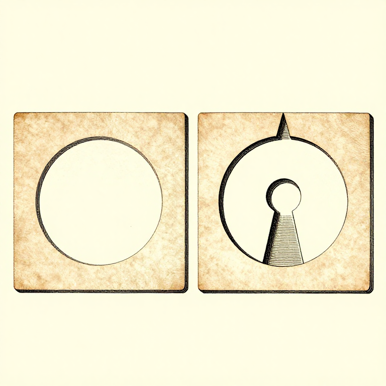


Designing For the Process: A Printable Part Is a Different Shape
A model drawn without thinking about printing can usually be printed. A model drawn WITH the process in mind prints faster, stronger, with no supports and a better surface — from the same amount of design effort.
Every rung before this one is a constraint: layers are weak in one direction, overhangs have a limit, holes come out small, corners warp, walls carry the load. Design is where those stop being problems to work around and become the rules the shape is drawn to.
That is the same move as designing a casting with draft angles, or a timber frame with wood movement allowed for. The process has a grain, and a good design runs with it.
İleri
4 hours
Talimatlar
1
1
Chamfer the bottom, fillet the rest
Chamfer the bottom, fillet the rest
A 45-degree CHAMFER on the bottom edge of a part is self-supporting, removes the elephant-foot bulge, and makes the part easier to insert into anything. It is close to free and almost always an improvement.
Fillets elsewhere reduce stress concentration and warping, exactly as a radiused corner does on any other part. Internal corners especially: a sharp internal corner is where a printed part cracks.
But do NOT fillet the bottom edge — a bottom fillet is an overhang that starts at 90 degrees, which is the one angle nothing can print. Chamfer at the bottom, fillet above it, and that single rule removes a lot of support material.
Bu adım için malzemeler:
 3D baskı filamenti (PLA)1 adet
Gerekli aletler:
 Masaüstü Bilgisayar
 3MF dosya dilimleme yazılımı
 Çapak alma aleti
2
2
Turn overhangs into bridges and teardrops
Turn overhangs into bridges and teardrops
A horizontal hole printed round has an unsupported arch at the top that sags. Printed as a TEARDROP — a circle with a 45-degree point on top — it is entirely self-supporting and needs no support at all.
A hexagonal hole does the same job and takes a nut. So does simply making the top of the hole a flat bridge rather than a curve, which prints well for the reasons the overhang rung gives.
The general form: wherever the model has a surface between 45 and 90 degrees, ask whether it can become a chamfer, a bridge, or a shape with a point on top. Nearly always it can, and nearly always the result is better than supporting it.
Bu adım için malzemeler:
3D baskı filamenti (PLA)1 adetGerekli aletler:
Masaüstü Bilgisayar3MF dosya dilimleme yazılımı Dijital Kumpas 6 İnç
3
3
Split the part where splitting helps
Split the part where splitting helps
A part that needs supports, or warps, or is too tall to be stable, can often be cut into two pieces that each print flat and are then glued or bolted.
Put the split where a joint is natural — at a change of section, behind a flange — and add a locating feature, a peg and socket or a dovetail, so the two halves cannot be assembled wrong. Design the clearance into one side only, as the tolerance rung sets out.
Splitting also lets each half be oriented for its own load path, which the orientation rung says is the highest-leverage decision available. A part split into two well-oriented halves can be stronger than the same part printed whole.
Bu adım için malzemeler:
3D baskı filamenti (PLA)1 adetGerekli aletler:
Masaüstü Bilgisayar3MF dosya dilimleme yazılımıDijital Kumpas 6 İnçÇapak alma aleti4
4
Use real hardware where it belongs
Use real hardware where it belongs
Printed threads are weak, printed bearings wear, and printed springs creep. Heat-set brass inserts, steel pins, real bearings and real fasteners cost very little and remove the weakest parts of a printed assembly.
Design the pocket for them from the start: a straight bore for an insert, a captive hex pocket for a nut, a shoulder for a bearing to seat against. A pocket designed in prints perfectly; one drilled afterwards splits the part along a layer.
Which is the whole argument of this batch. The printer is one process among several, it has specific strengths and specific limits, and the best results come from using it for what it is good at and something else for the rest.
Bu adım için malzemeler:
3D baskı filamenti (PLA)1 adet Karbon fiberli PETG filament1 adet
Gerekli aletler:
Masaüstü BilgisayarDijital Kumpas 6 İnç 3B yazıcı alet seti
Malzemeler
2- 4 adetYer Tutucu
- Karbon fiberli PETG filament%10 komisyon1 adetYer Tutucu
İlgili Blueprint'ler
Bu blueprint'ler bilgi paylaşır — teknikler, malzemeler veya ilkeler
CC0 Kamu Malı
Bu plan CC0 lisansıyla yayınlanmıştır. İzin almadan kopyalayabilir, değiştirebilir, dağıtabilir ve herhangi bir amaçla kullanabilirsiniz.
Planı üzerinden ürün satın alarak Maker'ı destekleyin, böylece Maker Komisyonu Satıcılar tarafından belirlenen komisyonu kazanırlar veya bu Planın yeni bir versiyonunu oluşturun ve gelir paylaşımı için kendi Planınıza bağlantı olarak ekleyin.