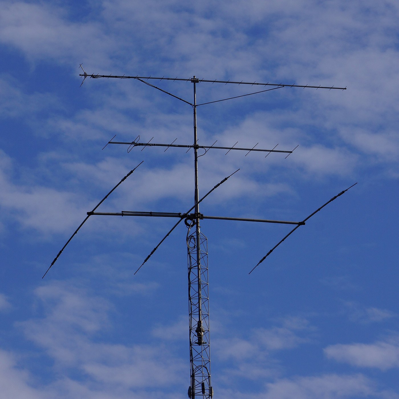


The Dipole and the Yagi-Uda Antenna
Talimatlar
Cut a half-wave dipole and find its resonance
Cut a half-wave dipole and find its resonance
Dimensions are the design. Start by computing them, then measure what you actually built.
- Pick a working frequency — 145 MHz is convenient, giving a wavelength of about 2.07 m.
- Cut two rods, each a quarter wavelength, and mount them end to end with a small gap, fed at the centre.
- Measure the resonant frequency with an antenna analyser.
- Compare with your calculation.
The measured resonance will be slightly LOWER than the free-space calculation predicts, meaning the antenna behaves as if it were longer than it is. This is the end effect: capacitance at the open ends of the rods adds to the electrical length. Real dipoles are cut around 95 percent of the theoretical half wavelength for exactly this reason, and the correction is larger for thicker rods.
This is why every antenna table gives a formula with an empirical constant rather than a clean derivation, and why any antenna is trimmed after building. Cut it deliberately long, measure, and shorten a few millimetres at a time — you can always remove metal and never add it back.Bu adım için malzemeler:
 Alüminyum çubuk2 m
 PVC Boru1 adet
 Koaksiyel kablo (RG-58)1 reel
 63/37 reçine özlü lehim teli1 reel
Gerekli aletler:
 Anten analizörü (SWR ölçer)
 Şerit Metre
 Dijital Kumpas 6 İnç
 Demir Testeresi
 Eğe Takımı
 Sütunlu Matkap
 Havya İstasyonu
 Şeffaf Koruyucu Gözlük
Map the radiation pattern and find the nulls
Map the radiation pattern and find the nulls
An antenna does not radiate equally in all directions, and knowing where it does not is as useful as knowing where it does.
- Set up a low-power transmitter on the dipole and a receiver with a field-strength meter several wavelengths away.
- Rotate the dipole through 360° in the horizontal plane, recording signal strength every 10°.
- Plot the result on polar axes.
- Now repeat rotating in the vertical plane through the rod axis.
You get a figure-of-eight: strong broadside to the rod, and a deep null straight off each END. No energy leaves along the axis of the wire at all.
The reason is worth holding onto: radiation comes from ACCELERATING charge, and the field radiated is strongest perpendicular to the direction of acceleration. The electrons oscillate along the rod, so nothing is radiated along it.
Those nulls are genuinely useful. Point the end of a dipole at an interfering station and it largely disappears, which is the basis of direction finding — you locate a transmitter far more precisely by rotating for a sharp null than for a broad peak, because a null is narrow and a peak is not.Bu adım için malzemeler:
 Milimetrik Kağıt1 pad
Gerekli aletler:
 Sinyal ÜreteciAnten analizörü (SWR ölçer)
 Laboratuvar Sınıfı Dijital Multimetre
 Spektrum Analizörü / FFT Yazılımı
 Manyetik pusulaŞerit MetreŞeffaf Koruyucu Gözlük
Match it, and find out what a mismatch actually costs
Match it, and find out what a mismatch actually costs
The antenna must present the right impedance to the feeder or power reflects back down the cable.
- Measure the feedpoint impedance of your dipole at resonance.
- Connect it to 50 Ω coaxial cable and measure the standing wave ratio.
- Now deliberately mismatch it — shorten one leg, or add a capacitor — and watch VSWR rise.
- Measure the power actually radiated at each setting.
A centre-fed half-wave dipole in free space is around 73 Ω, which is a decent but not perfect match to 50 Ω cable, giving a VSWR near 1.5. Power that is not accepted by the antenna travels back down the feeder and is lost as heat, or worse, returns to the transmitter output stage.
There is a second problem that a VSWR meter alone will not show you: coaxial cable is unbalanced and a dipole is balanced. Connect them directly and current flows on the OUTSIDE of the coax braid, so the feeder itself radiates — distorting the pattern you carefully measured and bringing RF back to your equipment.
A balun fixes it, and the simplest is several turns of the coax itself wound into a coil near the feedpoint — a choke that presents high impedance to common-mode current on the outside of the braid while doing nothing at all to the signal inside. Cheap, invisible on a schematic, and the difference between a working antenna and a puzzling one.Bu adım için malzemeler:
Koaksiyel kablo (RG-58)1 reel Ferrit toroid çekirdek2 adet
 Koaksiyel konnektör takımı (BNC / SO-239)1 takım
Gerekli aletler:
Anten analizörü (SWR ölçer)Laboratuvar Sınıfı Dijital Multimetre OsiloskopSpektrum Analizörü / FFT YazılımıHavya İstasyonuDijital Kumpas 6 İnçŞeffaf Koruyucu Gözlük
Add a reflector and a director, and get a beam
Add a reflector and a director, and get a beam
Two rods connected to nothing turn an omnidirectional antenna into a directional one.
- Mount a rod about 5 percent LONGER than the dipole, roughly 0.15 to 0.25 wavelengths behind it.
- Mount a second rod about 5 percent SHORTER, a similar distance in front.
- Neither is connected to anything.
- Repeat the polar pattern measurement of step 2.
The figure-of-eight collapses into a single forward lobe, several times stronger than the dipole alone, with a much weaker lobe behind. Nothing feeds these rods; the dipole’s own field induces current in them, and they re-radiate it with a phase shift set by their length.
The lengths are what set the phase. A rod longer than resonance is inductive and lags; a rod shorter is capacitive and leads. Place them at the right distance and the re-radiated waves arrive in phase with the dipole’s in front and out of phase behind — reinforcement forward, cancellation backward.
This is why the elements of a Yagi get progressively shorter toward the front, and why the spacings are as critical as the lengths. Adding more directors narrows the beam and adds gain, with diminishing returns — which is why a television aerial has many short elements at the front, one dipole, and a single longer reflector at the back. Now you can read one off a roof.Bu adım için malzemeler:
Alüminyum çubuk3 mPVC Boru1 adet Makine vidaları8 adet
Gerekli aletler:
Anten analizörü (SWR ölçer)Şerit MetreDijital Kumpas 6 İnçDemir TesteresiEğe TakımıSütunlu MatkapSinyal ÜreteciSpektrum Analizörü / FFT YazılımıŞeffaf Koruyucu GözlükTrade gain against bandwidth, and measure the cost
Trade gain against bandwidth, and measure the cost
Every added element buys directivity and spends something else. Find out what.
- Measure VSWR across a range of frequencies for the plain dipole and record the span where it stays below 2.
- Repeat for the three-element Yagi.
- Add two more directors and measure again — gain, front-to-back ratio and bandwidth.
- Tabulate all three antennas.
Gain and front-to-back ratio improve as elements are added, and usable bandwidth narrows sharply. A long Yagi is a high-Q structure: every parasitic element is a resonator, and the array only behaves correctly when all of them are near resonance together.
So an antenna carries the same trade the tuned circuit did in the first blueprint of this batch — sharper means narrower, and there is no way to have both. A television aerial covering many channels is deliberately built with thick or folded elements to lower its Q and broaden its response, accepting less gain in exchange for working across the whole band.
The general shape recurs across this entire batch: the tuned circuit, the IF strip, the antenna. Anything that selects strongly selects narrowly, and the engineering is always in choosing where on that curve to sit rather than in escaping it.Bu adım için malzemeler:
Alüminyum çubuk2 mMilimetrik Kağıt1 padMakine vidaları6 adetGerekli aletler:
Anten analizörü (SWR ölçer)Spektrum Analizörü / FFT YazılımıSinyal ÜreteciŞerit MetreDijital Kumpas 6 İnçLaboratuvar Sınıfı Dijital MultimetreŞeffaf Koruyucu GözlükMalzemeler
8- Yer Tutucu
- Yer Tutucu
- 1 reelYer Tutucu
- Yer Tutucu
- 1 padYer Tutucu
- 2 adetYer Tutucu
- Yer Tutucu
- 14 adetYer Tutucu
Gerekli Aletler
13- Yer Tutucu
- 1 vendor sell this, none ship to you yetYer Tutucu
- Yer Tutucu
- Yer Tutucu
- Yer Tutucu
- Yer Tutucu
- Yer Tutucu
- Yer Tutucu
- Yer Tutucu
- Yer Tutucu
- Yer Tutucu
- Yer Tutucu
- Yer Tutucu
İlgili Blueprint'ler
Bu blueprint'ler bilgi paylaşır — teknikler, malzemeler veya ilkeler




CC0 Kamu Malı
Bu plan CC0 lisansıyla yayınlanmıştır. İzin almadan kopyalayabilir, değiştirebilir, dağıtabilir ve herhangi bir amaçla kullanabilirsiniz.
Planı üzerinden ürün satın alarak Maker'ı destekleyin, böylece Maker Komisyonu Satıcılar tarafından belirlenen komisyonu kazanırlar veya bu Planın yeni bir versiyonunu oluşturun ve gelir paylaşımı için kendi Planınıza bağlantı olarak ekleyin.