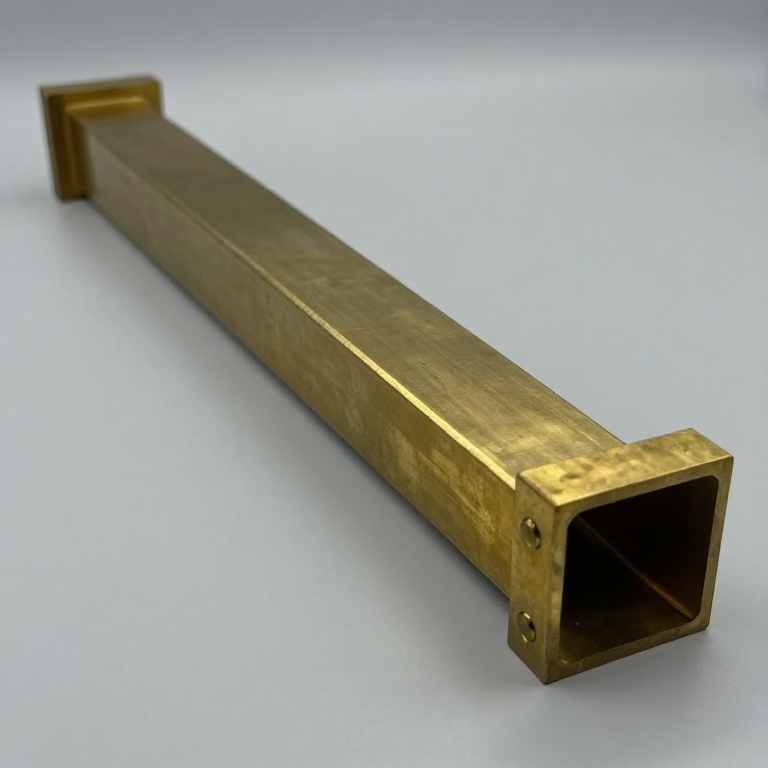


Waveguide and the Klystron
Talimatlar
Measure why coax fails at microwave frequencies
Measure why coax fails at microwave frequencies
Establish the loss that forces the change.
- Measure the insertion loss of a known length of coaxial cable at 1 MHz.
- Repeat at 100 MHz, then as high as your equipment reaches.
- Plot loss per metre against frequency.
Loss climbs steadily and then steeply. Two mechanisms are at work and both worsen with frequency: the skin effect confines current to an ever-thinner layer on the conductor surface, raising effective resistance; and the dielectric between the conductors absorbs energy directly, an effect that grows roughly in proportion to frequency.
The inner conductor is the real casualty. It is thin, it carries the full current, it is wrapped in insulation, and it therefore has nowhere to send its heat.
This is why microwave systems are built from rigid plumbing rather than cable, and why a satellite dish has its low-noise block mounted at the feed rather than indoors — you convert to a lower frequency at the antenna precisely so the run back to the receiver can be ordinary cable.Bu adım için malzemeler:
 Coaxial Cable (RG-58, 50 m)1 reel
 Graph Paper1 pad
Gerekli aletler:
 Signal Generator
 Spectrum Analyser / FFT Software
 Antenna Analyser (VSWR Meter)
 Digital Multimeter (Lab Grade)
 Digital Caliper 6-Inch
 Clear Safety Glasses
Build a rectangular waveguide and find its cutoff
Build a rectangular waveguide and find its cutoff
A hollow pipe is a high-pass filter whose corner frequency is set by its width.
- Make a rectangular waveguide section from sheet brass or copper — a good size for experiment is roughly 22 × 10 mm, which works above about 6.5 GHz.
- Fit a coupling probe at each end: a short quarter-wave pin projecting into the guide.
- Sweep frequency and measure transmission from end to end.
- Find the frequency below which nothing gets through.
Below the cutoff frequency the guide transmits nothing at all; above it, transmission is efficient. Cutoff for the dominant mode occurs when the free-space wavelength is twice the guide’s WIDE dimension — so the wide side alone sets the low-frequency limit, and the narrow side does not enter into it.
The reason a pipe does not short the signal is worth stating plainly: there is no inner conductor, so there is no circuit to short. The wave travels as a pattern of electric and magnetic fields that must satisfy the boundary condition that electric field is perpendicular to a conducting wall. Only certain patterns can do that, and only above a certain frequency does any pattern fit.
Reverse-engineering note: waveguide is always specified by its internal dimensions, never by an impedance, and its interior is often silver-plated. The plating is not decorative — at these frequencies all the current flows within a few micrometres of the surface, so the surface metal is the ONLY metal that matters.Bu adım için malzemeler:
 Brass Sheet (0.5mm)1 yaprak
 Copper Block (Cavity Stock)1 adet
 Silver Conductive Paint1 tube
Gerekli aletler:
Signal GeneratorSpectrum Analyser / FFT SoftwareAntenna Analyser (VSWR Meter)Digital Caliper 6-Inch Micrometer
 File Set
 Drill Press
 Hacksaw
 Soldering StationClear Safety Glasses
Find the standing wave and the guide wavelength
Find the standing wave and the guide wavelength
Measure inside the guide, and discover the wavelength is not what you expect.
- Cut a narrow slot along the CENTRE of the guide’s broad wall, parallel to the axis.
- Insert a small probe on a sliding carriage and feed its output to a detector.
- Terminate the far end with a short circuit and slide the probe along, recording detected level against position.
- Measure the distance between adjacent minima and double it.
The guide wavelength is LONGER than the free-space wavelength at the same frequency, and it stretches toward infinity as you approach cutoff. The wave is effectively zig-zagging down the pipe rather than travelling straight, so its progress along the axis is slower than its progress through space.
The slot position is not arbitrary and this is the detail worth remembering: a longitudinal slot in the centre of the broad wall cuts no current lines, so it does not disturb the fields and does not radiate. The same slot cut across the guide would interrupt the wall currents and turn the instrument into an antenna. Slotted lines are cut this way on purpose, and slotted-waveguide antennas are cut the opposite way on purpose.
This is the microwave version of the standing-wave measurement, and before network analysers existed it was how impedance was measured: the ratio of maximum to minimum gives VSWR, and the position of the minimum gives the phase.Bu adım için malzemeler:
Brass Sheet (0.5mm)1 yaprak Germanium Diode (1N34A)2 adetGraph Paper1 pad
Gerekli aletler:
Signal GeneratorSpectrum Analyser / FFT SoftwareAntenna Analyser (VSWR Meter)Digital Caliper 6-InchMicrometerFile SetDigital Multimeter (Lab Grade)Clear Safety GlassesBunch a beam in time, and understand the klystron
Bunch a beam in time, and understand the klystron
Velocity modulation converts a steady beam into a pulsating one without any grid switching it.
- Sketch the two-cavity klystron: an electron gun, a buncher cavity, a drift space, a catcher cavity and a collector.
- Follow one electron through: the buncher cavity’s RF field either speeds it up or slows it down depending on when it arrives.
- Reason about what happens to a stream of such electrons after they travel down the drift space.
Electrons that were speeded up catch those that were slowed down, so by the end of the drift space the uniform stream has sorted itself into dense bunches. No electron has been created or removed — they have merely been redistributed in time — and those bunches, arriving periodically at the catcher cavity, drive it hard and deliver useful RF power.
Notice what has happened to the transit-time problem. In a triode, transit time destroys control. Here the drift time IS the mechanism, and it is chosen deliberately: too short and the bunches have not formed, too long and they have passed through each other and dispersed.
The reflex klystron used in radar receivers folds this idea in half — one cavity, and a repeller electrode that turns the beam around and sends it back through the same cavity at the right moment. Fewer parts, easily tunable by varying the repeller voltage, and stable enough to serve as a local oscillator, which is exactly what the magnetron could not do.Bu adım için malzemeler:
Copper Block (Cavity Stock)1 adetGraph Paper1 padGerekli aletler:
Digital Caliper 6-InchMicrometerDigital Multimeter (Lab Grade) Oscilloscope 2-Channel 100MHzSpectrum Analyser / FFT SoftwareClear Safety Glasses
Make a horn, and close the loop back to the antenna
Make a horn, and close the loop back to the antenna
The wave has to leave the pipe and enter free space, and a sudden opening does that badly.
- Terminate a waveguide with a plain open end and measure the reflected power.
- Now fit a flared horn — a gradual expansion from guide dimensions to a much larger aperture.
- Measure reflected power again.
- Map the radiation pattern of both, as you did for the dipole earlier in this batch.
The abrupt opening reflects a substantial fraction back down the guide; the flared horn reflects very little and produces a clean, narrow beam. The horn is an impedance transformer — it changes the wave’s impedance gradually from that of the guide to that of free space, and gradual is the entire point.
That principle has appeared repeatedly in this batch under different names: the balun matching a dipole to coax, the IF transformer’s coupling, the tapered cable joint in the power batch. Wherever two media meet, an abrupt transition reflects and a gradual one does not.
And this is where the batch closes. The horn feeding a parabolic reflector is the standard microwave antenna — the dish is a mirror, the horn is the source at its focus, and beamwidth is set by dish diameter in wavelengths, exactly the same relationship that governed the Yagi. From the tuned circuit to the parabolic dish, every step has been the same two questions: how do you select one frequency, and how do you get energy across a boundary without losing it.Bu adım için malzemeler:
Brass Sheet (0.5mm)2 yaprak Aluminium Sheet (0.5mm)1 yaprakGraph Paper1 pad
Gerekli aletler:
Signal GeneratorSpectrum Analyser / FFT SoftwareAntenna Analyser (VSWR Meter) RF Power Density MeterDigital Caliper 6-InchFile SetHacksaw
 Tape Measure (5 m)Clear Safety Glasses
Malzemeler
7- Yer Tutucu
- 1 padYer Tutucu
- 4 yaprakYer Tutucu
- Yer Tutucu
- 1 tubeYer Tutucu
- 2 adetYer Tutucu
- 1 yaprakYer Tutucu
Gerekli Aletler
14- Yer Tutucu
- Yer Tutucu
- Yer Tutucu
- Yer Tutucu
- Yer Tutucu
- Yer Tutucu
- Yer Tutucu
- Yer Tutucu
- Yer Tutucu
- Yer Tutucu
- Yer Tutucu
- Yer Tutucu
- 1 vendor sell this, none ship to you yetYer Tutucu
İlgili Blueprint'ler
Bu blueprint'ler bilgi paylaşır — teknikler, malzemeler veya ilkeler

CC0 Kamu Malı
Bu plan CC0 lisansıyla yayınlanmıştır. İzin almadan kopyalayabilir, değiştirebilir, dağıtabilir ve herhangi bir amaçla kullanabilirsiniz.
Planı üzerinden ürün satın alarak Maker'ı destekleyin, böylece Maker Komisyonu Satıcılar tarafından belirlenen komisyonu kazanırlar veya bu Planın yeni bir versiyonunu oluşturun ve gelir paylaşımı için kendi Planınıza bağlantı olarak ekleyin.