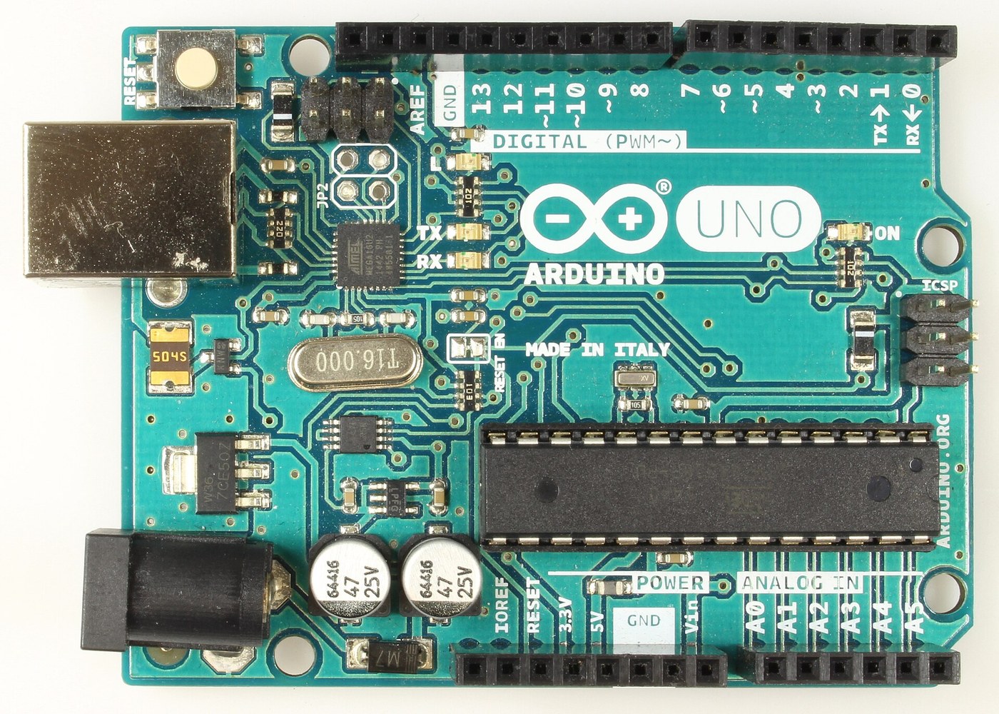


Arduino Uno R3: Assembled from Arduino's Open UNO-TH Rev3e Design Files and Flashed over ICSP
Інструкції
Get the bare board
Get the bare board
Матеріали для цього кроку:
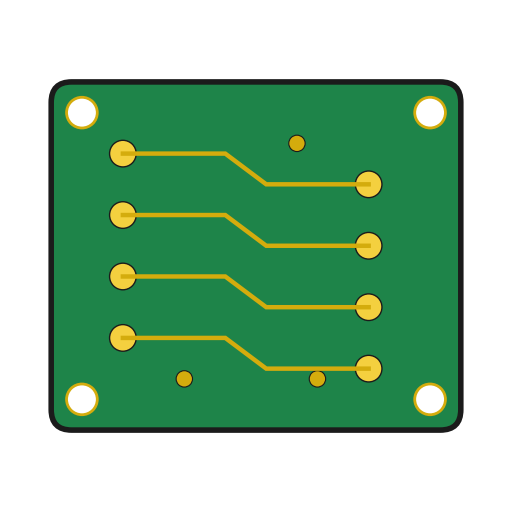 Друкована плата1 UNO-TH Rev3e layout
Необхідні інструменти ({count})
 Ювелірна лупа
Fit the small surface-mount parts
Fit the small surface-mount parts
Матеріали для цього кроку:
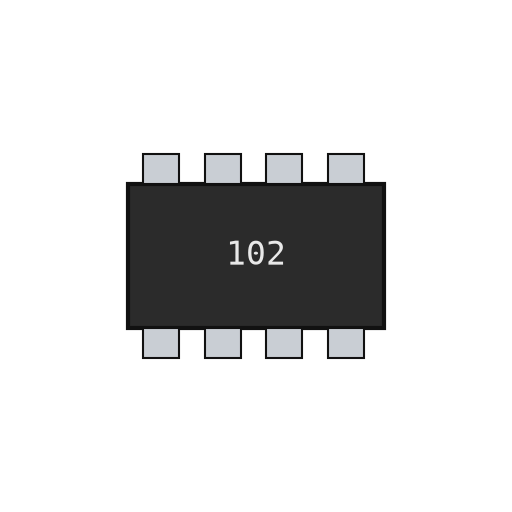 Резисторна збірка4 RN1-RN4
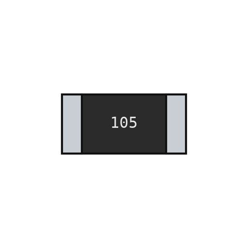 Чип-резистор2 1M
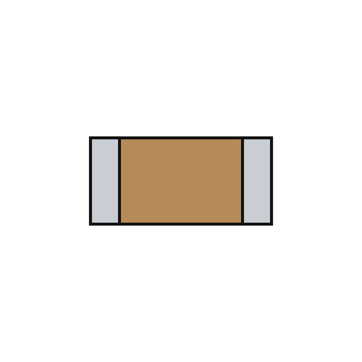 Керамічний чип-конденсатор11 7x100n, 2x1u, 2x22p
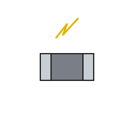 Чип-варистор2 Z1, Z2
 Феритова намистина1 L1
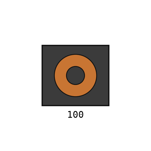 SMD-котушка індуктивності1 L2
 SMD-діод2 D2, D3
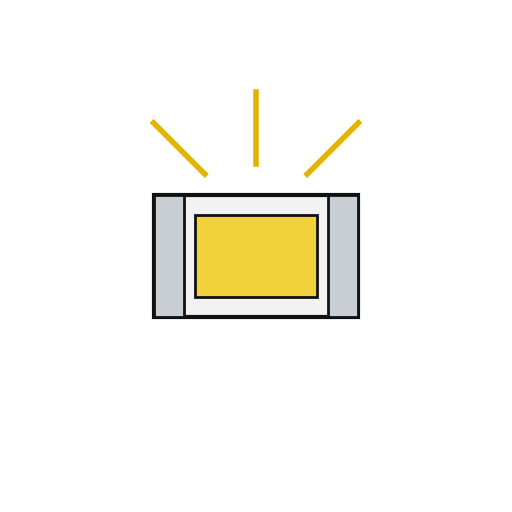 Чип-світлодіод4 1 green, 3 yellow
 Дріт припою1 a little
Необхідні інструменти ({count})
 Флюс
 Пінцет із гострими губками
 Термоповітряна паяльна станція
 ПаяльникЮвелірна лупа
Fit the power and chip parts
Fit the power and chip parts
Матеріали для цього кроку:
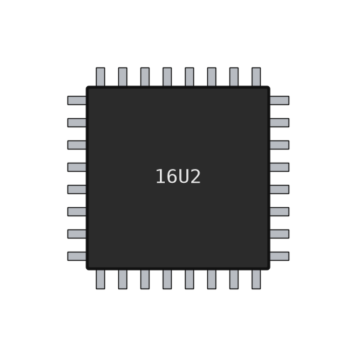 Мікроконтролер ATmega16U21 U3
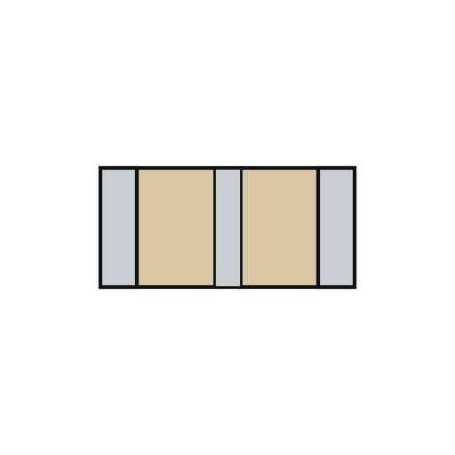 П’єзокерамічний резонатор1 Y2
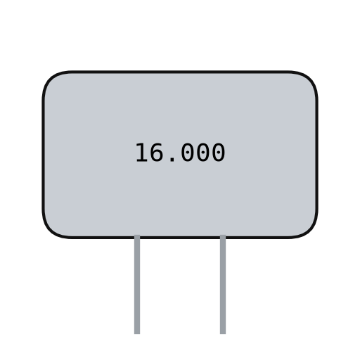 Кварцовий резонатор1 Y1
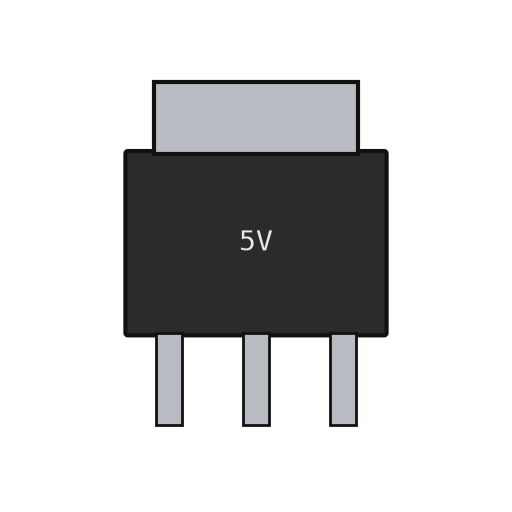 Лінійний стабілізатор напруги2 U1 5 V, U2 3.3 V
 Мікросхема операційного підсилювача1 U5 LMV358
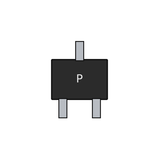 P-канальний МОН-транзистор1 T1SMD-діод1 D1 M7
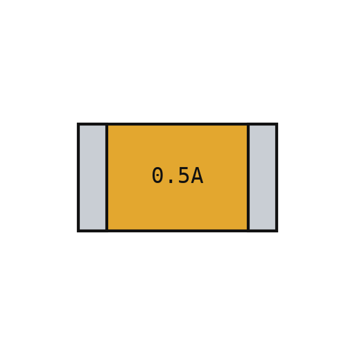 Самовідновлюваний запобіжник1 F1
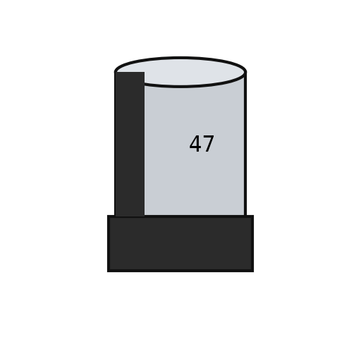 Полярний чип-конденсатор2 PC1, PC2Дріт припою1 a little
Необхідні інструменти ({count})
ФлюсПінцет із гострими губкамиТермоповітряна паяльна станціяПаяльникЮвелірна лупаFit the through-hole parts
Fit the through-hole parts
Матеріали для цього кроку:
 Гніздо USB-B1 X2
 Гніздо живлення1 X1
 Кнопка1 RESET
 Штирова лінійка6 10x1, 2x 8x1, 6x1 female; 2x 3x2 ICSP
 Мікроконтролер ATmega328P1 ZU4Дріт припою1 as needed
Необхідні інструменти ({count})
ПаяльникFlash and check
Flash and check
Матеріали для цього кроку:
 Прошивка Arduino Uno1 download
Необхідні інструменти ({count})
 Мультиметр
 Програматор AVR ISP
 Кабель USB-B
The blink test
The blink test
Необхідні інструменти ({count})
Кабель USB-BМатеріали
24- 1 UNO-TH Rev3e layoutЗаповнювач
- 4 RN1-RN4Заповнювач
- 2 1MЗаповнювач
- 11 7x100n, 2x1u, 2x22pЗаповнювач
- 2 Z1, Z2Заповнювач
- Заповнювач
- Заповнювач
- 1 D1 M7Заповнювач
- 4 1 green, 3 yellowЗаповнювач
- 1 as neededЗаповнювач
- Заповнювач
- Заповнювач
- Заповнювач
- 2 U1 5 V, U2 3.3 VЗаповнювач
- 1 U5 LMV358Заповнювач
- Заповнювач
- Заповнювач
- 2 PC1, PC2Заповнювач
- 1 X2Заповнювач
- Заповнювач
- Заповнювач
- Заповнювач
- Заповнювач
- 1 downloadЗаповнювач
Необхідні інструменти
8- Заповнювач
- Заповнювач
- Заповнювач
- Заповнювач
- 2 vendors sell this, none ship to you yetЗаповнювач
- Заповнювач
- Заповнювач
- 1 vendor sell this, none ship to you yetЗаповнювач
За цим кресленням виготовляють
Пов'язані креслення
Ці креслення діляться знаннями — техніки, матеріали або принципи
CC0 Суспільне надбання
Це креслення випущено під ліцензією CC0. Ви можете вільно копіювати, змінювати, поширювати та використовувати цю роботу для будь-яких цілей без запиту дозволу.
Підтримайте мейкера, купуючи продукти через його креслення, де він отримує Комісію мейкера встановлену вендорами, або створіть нову ітерацію цього креслення та включіть його як зв'язок у власне креслення для розподілу доходу.