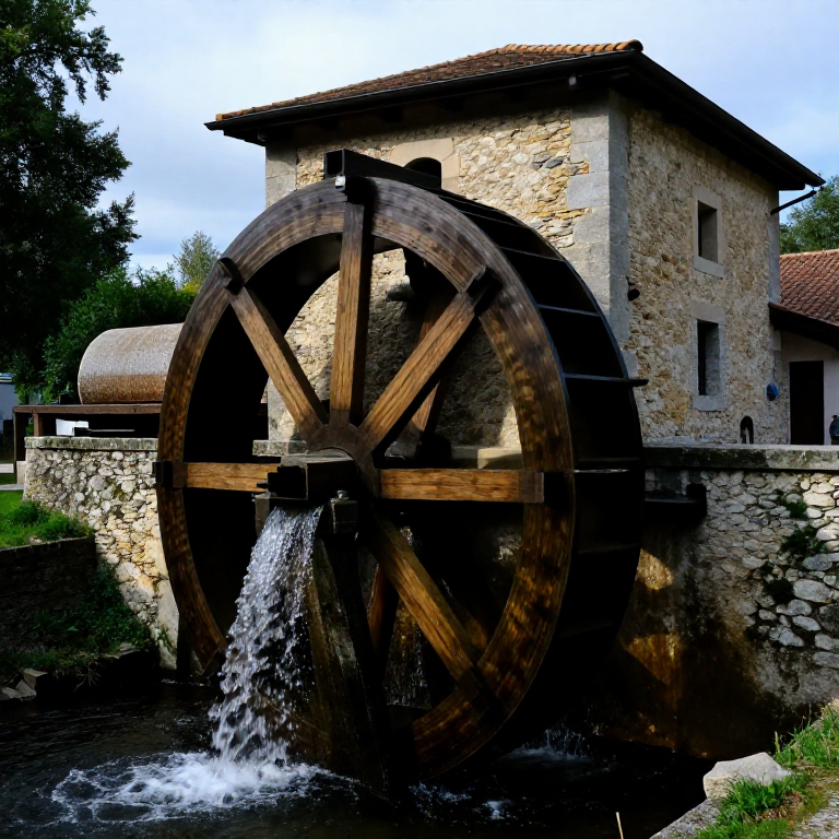
Building a Roman Undershot Water Mill — Grain Milling by Hydraulic Power
The Roman water mill is the first widespread application of non-human, non-animal mechanical power in history. While the ancient Greeks described water mills theoretically and isolated examples existed in Hellenistic times, it was the Romans who deployed them systematically and at industrial scale. The Barbegal mill complex near Arles in southern France, dating to around 100–300 AD, consisted of 16 overshot water wheels arranged in two parallel rows descending a hillside — the largest known concentration of mechanical power in antiquity, capable of producing approximately 4.5 tonnes of flour per day to supply the Roman city of Arles.
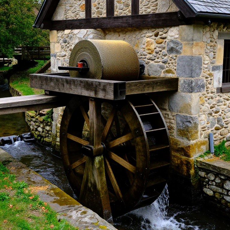
An undershot water mill uses the kinetic energy of flowing water striking the lower paddle blades of the wheel, rather than the potential energy of water falling on the top of an overshot wheel. Undershot wheels are simpler to build (no millrace infrastructure needed above wheel height) and can be deployed wherever there is a fast-flowing river or millstream, but they are less efficient (approximately 15–30% efficiency) than overshot wheels (60–85%). Roman engineers used undershot wheels for river mills on large rivers like the Tiber in Rome itself — where building a millrace of sufficient height was impractical.
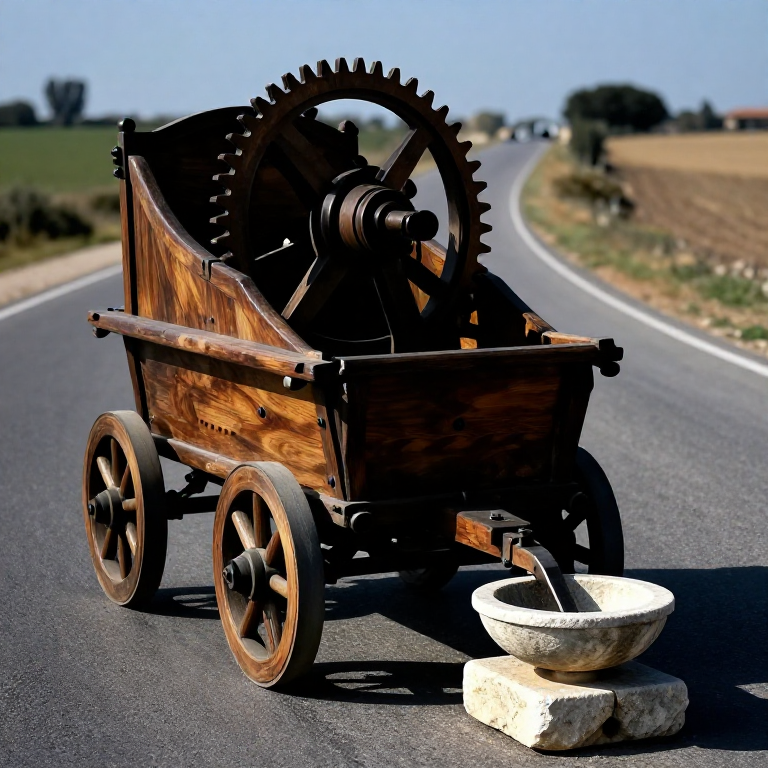
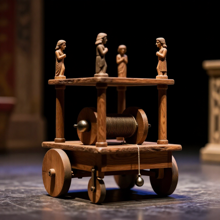
The key mechanical innovation of the Roman mill is the right-angle gearing system that converts the horizontal rotation of the water wheel into the vertical rotation of the millstone. The main wheel's horizontal axle carries a crown wheel (a gear with teeth projecting vertically from its face). A lantern pinion (a cage of cylindrical rungs between two discs) meshes with the crown wheel at 90 degrees, transferring rotation to a vertical drive shaft that turns the upper millstone. This crown-wheel-and-lantern-pinion system was the fundamental gear unit of mill technology for 1,500 years after the Romans.
Інструкції
Select the mill site and measure water flow
Select the mill site and measure water flow
Choose a site where the river is fast-flowing and narrow — the power available from an undershot wheel is proportional to the water velocity cubed and to the wheel width. A current of 1.5 m/s (a brisk walking pace) in a 2-metre wide channel provides roughly 3–5 kW of available hydraulic power; at 2 m/s the same channel provides nearly double that. Measure velocity by timing a floating stick over a known distance. Assess the bank geometry: the mill building must be founded on solid ground above flood level, with the wheel projecting into the flow. In Rome, many undershot mills were built on barges moored in the Tiber, allowing them to be repositioned to find the strongest current — the mola navalis (ship mill) form.
Build the mill building foundation and floor
Build the mill building foundation and floor
Found the mill building on stone or timber piles set back from the river bank. The floor must be elevated above the highest flood level — a Roman mill that floods loses its millstones and gear timbers. Pour a concrete floor slab or lay stone flags over the foundation. The floor has a central aperture for the vertical millstone drive shaft to pass through from the waterwheel below. Build two heavy stone or timber plinths on either side of the aperture to support the main wheel axle bearings — these must carry the entire weight of the water wheel (which may be 500–2,000 kg for a full-scale Roman mill wheel) plus the dynamic forces from the water.
Матеріали для цього кроку:
 Calcium Carbonate (Crushed Limestone)60 кг
 Coarse Sand40 кг
Turn or shape the main wheel axle from dense hardwood
Turn or shape the main wheel axle from dense hardwood
The main axle is the most critically stressed component of the mill — it must transmit the entire torque of the wheel to the crown wheel gear without twisting or breaking. Select a dense, straight-grained hardwood log (oak or elm) approximately 15–20 cm in diameter and long enough to span across the wheel plus sufficient extension for the crown wheel and bearing journals. Hew the log to a consistent octagonal cross-section using an adze, then round the bearing journals (the sections that rest in the bearing blocks) with a drawknife to a smooth cylinder. The journals must be smooth and round to minimise bearing friction — coat them with tallow mixed with beeswax as a bearing lubricant.
Матеріали для цього кроку:
 Hardwood Block4 штук
Необхідні інструменти ({count})
 Hand Saw
 Sharp Knife
Build the water wheel from hardwood spokes and paddles
Build the water wheel from hardwood spokes and paddles
Build the wheel in two stages: first the structural frame (hub, spokes, felloes), then the paddle blades. Attach 8–12 radial spokes of straight-grained ash to the central hub (the axle) by mortising them into squared sockets hewn into the axle. Each spoke should be approximately half the wheel's radius in length — for a 2.5-metre diameter wheel, spokes are about 1.1 metres long. Connect the outer ends of the spokes with curved felloe segments to form the wheel rim. The spokes and felloes must be assembled in a true circle — check with a compass (a cord tied to the axle) that all spoke tips are at the same radius. Then attach flat wooden paddle blades (approximately 30 cm wide × 30 cm tall) to the rim, evenly spaced around the circumference — typically 12–16 paddles for a 2.5-metre wheel.
Матеріали для цього кроку:
 Hardwood Shaft (2m)6 штук
 Iron Nails80 штук
Cut the crown wheel teeth from hardwood pegs
Cut the crown wheel teeth from hardwood pegs
The crown wheel is a large disc of hardwood mounted on the axle, with radial teeth projecting from one face — perpendicular to the axle. For a wheel with 30 teeth, the tooth spacing around the crown wheel circumference must be perfectly equal — lay out the tooth positions by dividing the crown wheel face into 30 equal sectors using geometry (inscribed regular polygon). Drill holes at each tooth position and press-fit wooden tooth pegs (approximately 4 cm diameter, 8 cm long) of dense apple or pear wood — the hardest available fruit woods — through the holes and wedge from behind. Fruit wood teeth against the softer lantern pinion rungs provides a good wear coupling and the teeth can be replaced individually when worn without rebuilding the entire gear.
Необхідні інструменти ({count})
 Awl
AwlBuild the lantern pinion on the vertical drive shaft
Build the lantern pinion on the vertical drive shaft
The lantern pinion (trundle) is the small gear on the vertical shaft that meshes with the crown wheel. It consists of two circular wooden discs separated by a row of cylindrical wooden rungs (the lanterns), arranged in a cylinder of rungs that the crown wheel teeth push past. For a crown wheel of 30 teeth and a speed ratio of 5:1 (giving the millstone 5 rotations per wheel rotation), the pinion needs 6 rungs. Make the rung diameter approximately 70% of the crown wheel tooth width — the rung-to-tooth interference drives the shaft. The vertical drive shaft is straight hardwood, 5–8 cm diameter, running from the lantern pinion at the bottom to the millstone coupling at the top, supported in a lower bearing block in the mill floor and an upper bearing block in a ceiling beam.
Матеріали для цього кроку:
Hardwood Block2 штукInstall and level the bedstone (lower millstone)
Install and level the bedstone (lower millstone)
The bedstone (lower millstone) is fixed and does not rotate. It must be set absolutely level — any tilt causes the upper stone to bear heavily on one side, wearing unevenly and producing coarse flour on one side and dust on the other. Millstones were quarried from hard volcanic rock (buhrstone) or dense sandstone. Roman millstones ranged from 50 cm diameter (domestic mills) to 90–120 cm diameter (commercial mills). Mount the bedstone on a sturdy stone or masonry plinth at the correct working height. Level it using a water level checked in multiple directions. Fit the bedstone with a central iron spindle socket (the rynd) that receives the drive shaft — the shaft passes through the bedstone centre without rotating it.
Матеріали для цього кроку:
 Grinding Stone1 штука
Dress the millstone grinding faces with furrows
Dress the millstone grinding faces with furrows
Both millstone faces must be dressed with a pattern of furrows (lands and grooves) that perform three functions: cut the grain, pump air through the grinding zone, and channel flour to the stone periphery for collection. The classic Roman/medieval furrow pattern consists of radial master furrows (approximately 6 per quadrant = 24 total) with smaller parallel cracking furrows between them (the stitching). Use a sharp iron mill bill (a narrow pick-like tool with two cutting edges) to dress each furrow to a depth of approximately 5 mm at the eye (centre), tapering to 0 mm at the periphery. Both stones must have matching furrow patterns that work together as scissors — dress them to the same pattern layout.
Fit the runner stone (upper millstone) onto the drive shaft
Fit the runner stone (upper millstone) onto the drive shaft
The runner stone (upper millstone) rotates and must be coupled to the vertical drive shaft through an iron rynd — a cross-bar fitting that sits in a recess in the stone's upper face and is driven by a pin from the shaft. Lift the runner stone using a crane (a timber gin pole and rope-and-pulley system) and lower it onto the bedstone, threading the shaft through the central eye. The runner stone must float just above the bedstone — the gap between the faces (the grinding gap) determines flour fineness. Start with a gap of approximately 0.5 mm for fine flour; increase for coarser grades. Adjust the gap by raising or lowering the drive shaft using a beam lever bearing arrangement (the bridging box) — this is the miller's primary adjustment control.
Матеріали для цього кроку:
Grinding Stone1 штукаBuild the hopper and shoe for grain feeding
Build the hopper and shoe for grain feeding
Build a funnel-shaped hopper above the millstones to feed grain at a controlled rate. The hopper should hold at least 20–30 kg of grain and feed it through a rectangular shoe (a vibrating wooden chute) into the millstone eye. The shoe must vibrate — mill the grain at the correct feed rate — to prevent bridging (grain clogging in the hopper). Attach the shoe to a dancer peg that bears on the rotating upper stone surface: as the stone turns, the eccentric surface makes the peg bounce, which rattles the shoe. This self-regulating feed mechanism — the shoe feeds faster when the stones grind faster — is an elegant Roman engineering solution that prevented stone-to-stone contact from over-milling.
Матеріали для цього кроку:
Hardwood Block3 штукInstall the flour tun (collecting box) around the millstones
Install the flour tun (collecting box) around the millstones
Enclose the millstones in a circular wooden tun (box) that catches flour as it flies centrifugally off the spinning stone periphery. The tun should be approximately 20 cm taller than the combined bedstone and runner stone height, with a close-fitting lid through which the hopper projects. Fit the tun with a spout at the base on one side to discharge collected flour into sacks or bins. The enclosure serves two purposes: it captures all the flour (preventing waste and dust inhalation by the miller) and it keeps vermin out of the grinding zone. Line the inner tun surface with smooth hardwood or copper sheet to prevent flour sticking and to facilitate cleaning.
Commission the mill with a test grinding run
Commission the mill with a test grinding run
Open the sluice gate or divert the millstream to engage the undershot wheel. Allow the wheel to run without grain for several minutes — observe the gear meshing, bearing temperatures, and shaft alignment. Any vibration or knocking indicates a misaligned gear or an unbalanced stone. Feed a small amount of grain (2–3 kg) through the hopper and observe the flour produced. Check flour fineness: run it through a fine linen sieve (bolting cloth) — the fraction that passes is fine flour (farina); the coarser fraction is middlings. If the flour is too coarse, reduce the stone gap by lowering the bridging box. A Roman commercial water mill of 2.5 m wheel diameter running in a 1.5 m/s stream could produce approximately 150–200 kg of flour per hour — enough to supply 400 people's daily bread.
Матеріали
6- Заповнювач
- Заповнювач
- 9 штукЗаповнювач
- 6 штукЗаповнювач
- 80 штукЗаповнювач
- 2 штукЗаповнювач
Необхідні інструменти
3- Заповнювач
- Заповнювач
- Заповнювач
Матеріали з пов'язаних креслень
Пов'язані креслення
Ці креслення діляться знаннями — техніки, матеріали або принципи
Related blueprints
Other builds that share materials, tools, or techniques with this one.
CC0 Суспільне надбання
Це креслення випущено під ліцензією CC0. Ви можете вільно копіювати, змінювати, поширювати та використовувати цю роботу для будь-яких цілей без запиту дозволу.
Підтримайте мейкера, купуючи продукти через його креслення, де він отримує Комісію мейкера встановлену вендорами, або створіть нову ітерацію цього креслення та включіть його як зв'язок у власне креслення для розподілу доходу.