Співпраця
МИСТЕЦТВО
КРАСА ТА ЗДОРОВ'Я
РЕМЕСЛО
КУЛЬТУРА ТА ІСТОРІЯ
РОЗВАГИ
СЕРЕДОВИЩЕ
ЇЖА ТА НАПІЇ
ЗБОРНА ІНЖЕНЕРІЯ
НАУК
СПОРТ
ТЕХНОЛОГІЯ
НОСИМО
Shifting-Gear Grinding-Disk Churn: One Crank Wheel Is Thrown Into Gear With the Wings Below, the Grinding Disk Above, or Both
Buttercup

Створено

Buttercup

12. листопад 2026IE
8
0
0
0
0

Shifting-Gear Grinding-Disk Churn: One Crank Wheel Is Thrown Into Gear With the Wings Below, the Grinding Disk Above, or Both

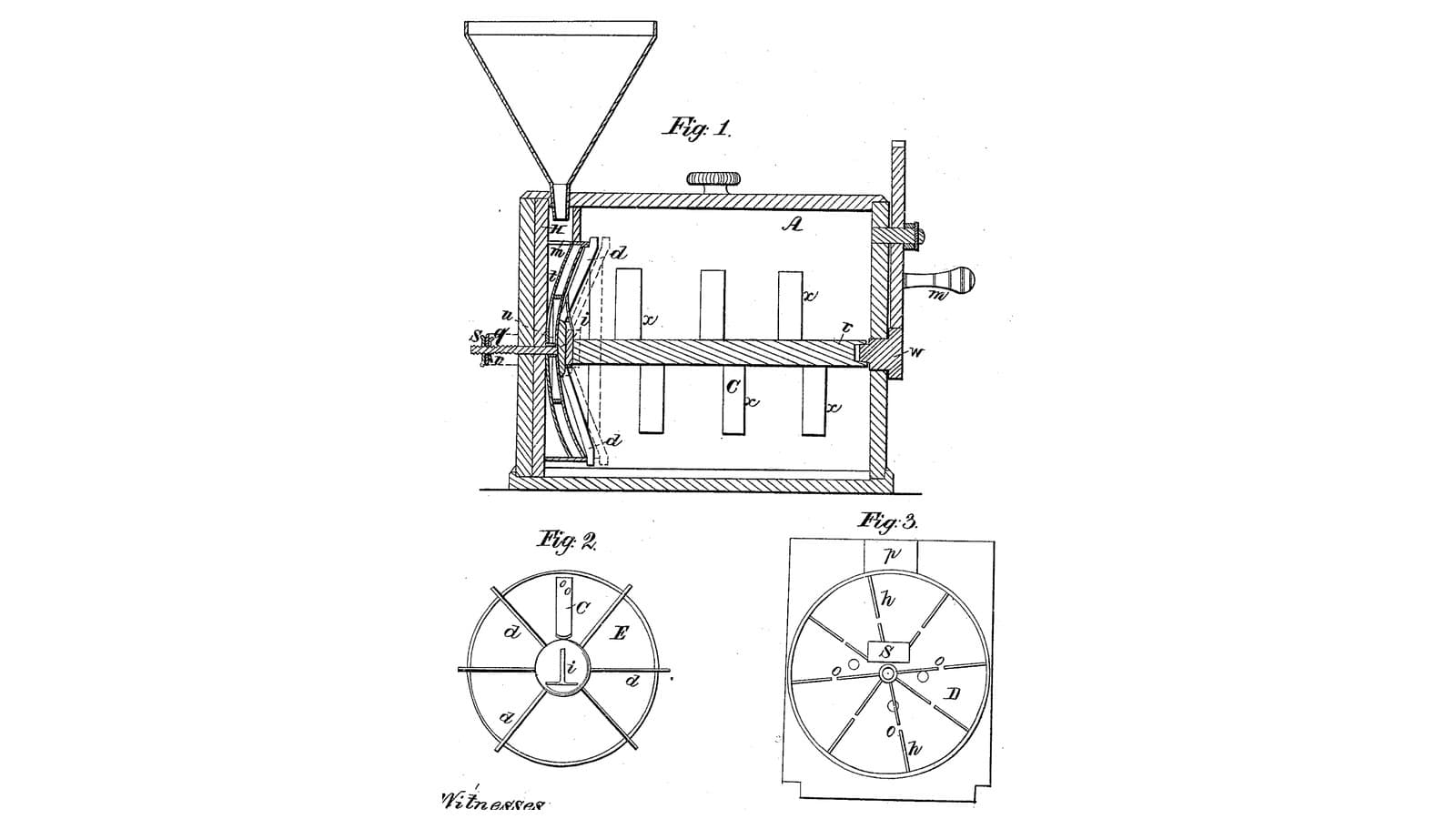
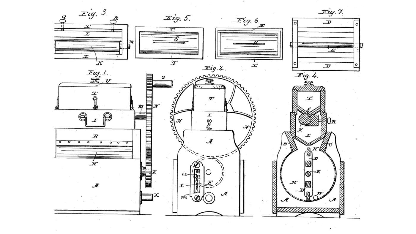
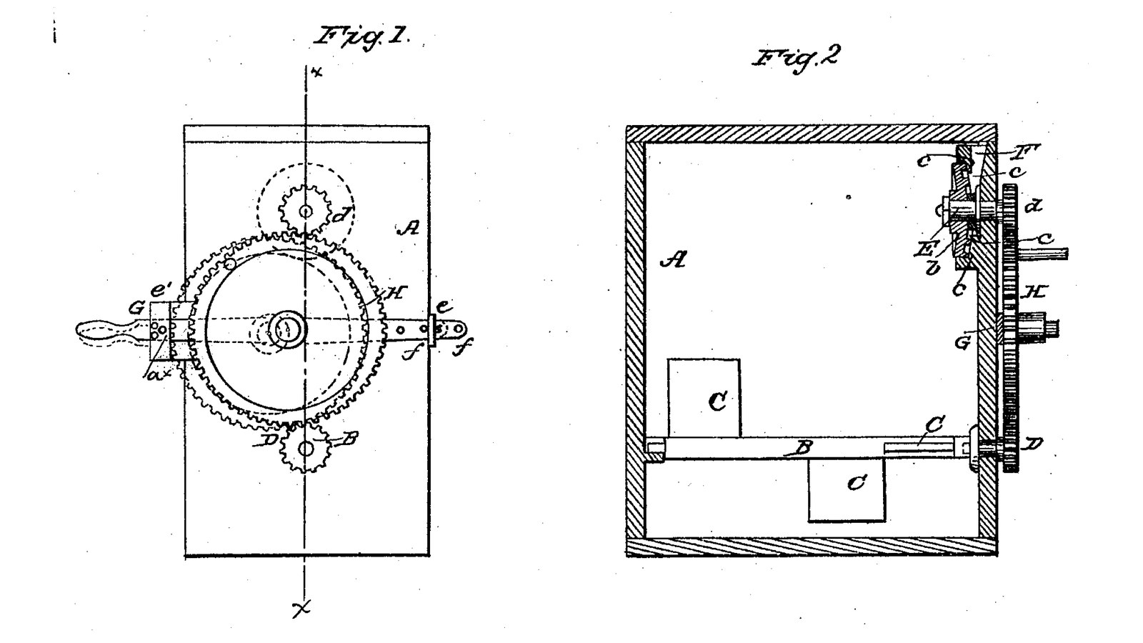
John Fowler and W. L. Walter of Homer, New York, received US 32,939, dated 30 July 1861, for a box churn with two working parts on one crank. High in the box a turning disk grinds the cream poured from a hopper against a fixed ribbed disk, and the cream falls below, out of their way; low in the box a shaft of wings gathers the butter. The crank wheel rides on a bar that slides and tilts in two guides on the box's side, so it can be put in gear with the disk alone, the wings alone, or both, and pinned there. The patent gives no sizes; every size here is ours.
Просунутий
About 3 days

Інструкції

1

One wheel, two pinions

Завантаження блокнота Jupyter…
2

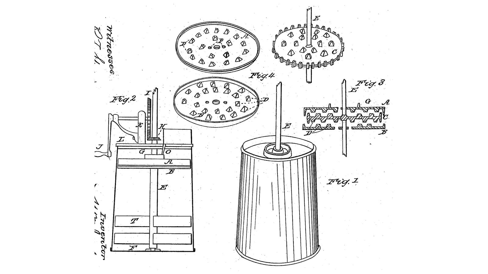
Cream ground once between disks as it is poured in, three months before

Jackson and Clarke grind the cream in a disk pack over the beaters. Fowler and Walter put the disks to one side and let one crank drive either disks or wings.
3

Read US 32,939

"By having the wheel H, attached to the bar G, and the latter arranged as shown, the disk b, may be rotated without the shaft B, or the latter may be rotated without the former or both rotated simultaneously as may be desired. This is an important feature of the invention for it is frequently necessary to use the disks without the wings or gatherers and vice versa."
4

Body A and lid

Glue up a hardwood box A 300 mm wide, 360 long and 320 deep inside, from 20 mm boards, joints sealed with silicone sealant. Bore one end 16.6 mm at 80 and 240 mm above the inside floor on its centre line for the shafts B and E, and the far end 16.6 mm at 80 mm for B's other bearing. Cut a hardwood lid with a 14 mm hole 25 mm off the centre line and 13 mm in from the geared end, for the hopper's spout.

Матеріали для цього кроку:

Дошка з твердої деревиниДошка з твердої деревини4 штук
Столярний клейСтолярний клей1 штука
Силіконовий герметикСиліконовий герметик1 штука
Шурупи по деревуШурупи по дереву30 штук

Необхідні інструменти ({count})
Циркулярний верстатЦиркулярний верстат
Акумуляторний дрильАкумуляторний дриль
Набір сверделНабір свердел
Набір перових сверделНабір перових свердел
Струбцина з напрямноюСтрубцина з напрямною
Набір викрутокНабір викруток
РулеткаРулетка
5

Shaft B with wings C and pinion D

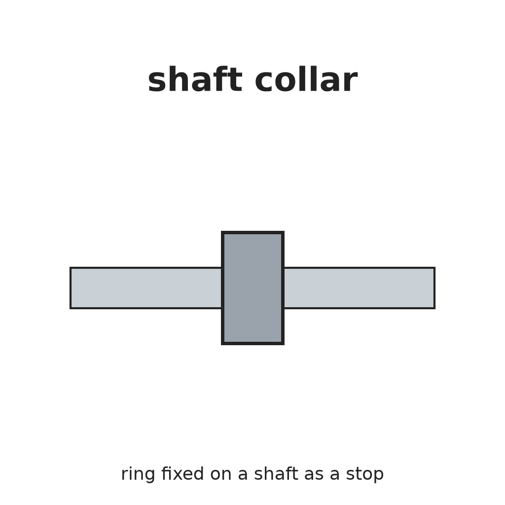
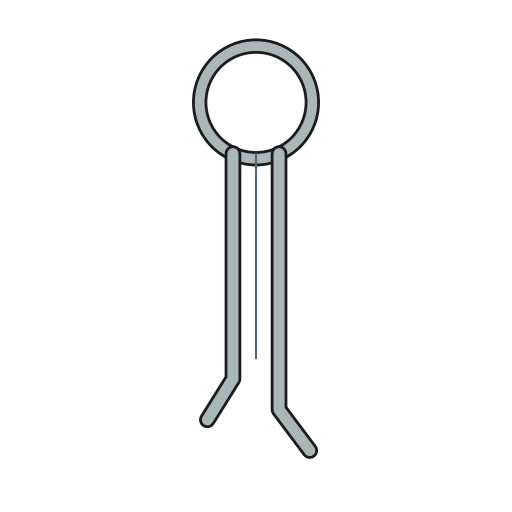
Cut a 16 mm stainless shaft B 432 mm long. Screw two pairs of hardwood wings C 70 x 80 x 20 mm through hardwood hubs on it, a quarter turn apart, one pair 70 to 150 mm from the geared end and one 220 to 300. Run it through both ends with shaft collars and pin a pinion D on its outer end 6 mm outside the box.

Матеріали для цього кроку:

Пруток із нержавкої сталіПруток із нержавкої сталі1 штука
Дошка з твердої деревиниДошка з твердої деревини1 штука
Шурупи по деревуШурупи по дереву8 штук
Shaft CollarShaft Collar2 штук
ШплінтШплінт2 штук
Філамент PETGФіламент PETG1 штука

Необхідні інструменти ({count})
3D-принтер FDM3D-принтер FDM

Циркулярний верстатЦиркулярний верстат
Акумуляторний дрильАкумуляторний дриль
Набір сверделНабір свердел
Ножівка по металуНожівка по металу
Напилки (ручний напилок)Напилки (ручний напилок)
Набір викрутокНабір викруток
6

Print the pinions D and d (two)

A pinion: 16 teeth, module 2.5, 12 mm thick, 16.2 mm bore. Print two. PETG, 0.2 mm layers, 30 % infill, 4 walls.
Файл дизайнуSTLCC0 - Free
7

Print the grinding disk b

The turning disk: 110 mm across, 6 thick, with two rings of ledges c 3 mm high at 40 and 50 mm out on its face, 16.2 mm bore. PETG, 0.2 mm layers, 30 % infill, 4 walls.
Файл дизайнуSTLCC0 - Free
8

Print the hopper F

The hopper: a funnel 80 mm across on a 14 mm spout long enough to reach behind the fixed disk. PETG, 0.2 mm layers, 30 % infill, 4 walls.
Файл дизайнуSTLCC0 - Free
9

Disks a and b, shaft E, pinion d and hopper F

Cut a 6 mm HDPE disk a 120 mm across with a 60 mm centre opening, glue twelve HDPE ribs 26 x 6 x 3 mm radially on its face, and screw it inside the geared end on three 10 mm stainless standoffs 25 mm long, around the upper shaft hole, ribs inward. Cut a 16 mm stainless shaft E 120 mm long, push it through the end and the disk a's opening, pin the disk b on its inner end with its ledges 3 mm from a's ribs, and the pinion d on its outer end. Set the hopper F in the lid so its spout drops into the space behind a, beside the shaft.

Матеріали для цього кроку:

Лист ПЕВГЛист ПЕВГ1 штука
Столярний клейСтолярний клей1 штука
Пруток із нержавкої сталіПруток із нержавкої сталі2 штук
Шурупи по деревуШурупи по дереву3 штук
ШплінтШплінт2 штук
Shaft CollarShaft Collar1 штука
Філамент PETGФіламент PETG1 штука

Необхідні інструменти ({count})
3D-принтер FDM3D-принтер FDM
КомпасКомпас
ЕлектролобзикЕлектролобзик
Набір перових сверделНабір перових свердел
Ножівка по металуНожівка по металу
Акумуляторний дрильАкумуляторний дриль
Набір сверделНабір свердел
Набір викрутокНабір викруток
10

Print the crank wheel H

The crank wheel: 48 teeth, module 2.5, 12 mm thick, 12.2 mm bore. PETG, 0.2 mm layers, 30 % infill, 4 walls.
Файл дизайнуSTLCC0 - Free
11

Bar G, guides e, e', wheel H and pin a*

Cut a mild steel flat bar G 470 x 24 x 6 mm, drill it 12.2 mm for H's axle 210 mm from one end and a row of 6 mm holes near the other end. Make two hardwood guides: e, a block with a slot just wide enough for the bar, screwed to the geared end level with the gap between the pinions; e', with a slot 60 mm tall so the bar's end can rise and fall, and a row of 6 mm holes across it. Fit a 12 mm stainless axle in the bar, the wheel H on it between the two pinions, and a crank handle on H's face. Slide the bar into the guides and hold it with a 6 mm pin a* through e' and the bar.

Матеріали для цього кроку:

Смуга з маловуглецевої сталіСмуга з маловуглецевої сталі1 штука
Дошка з твердої деревиниДошка з твердої деревини1 штука
Шурупи по деревуШурупи по дереву8 штук
Пруток із нержавкої сталіПруток із нержавкої сталі1 штука
ШплінтШплінт2 штук
Шканти з твердої деревиниШканти з твердої деревини1 штука
Філамент PETGФіламент PETG1 штука

Необхідні інструменти ({count})

3D-принтер FDM3D-принтер FDM
Ножівка по металуНожівка по металу
Напилки (ручний напилок)Напилки (ручний напилок)
Слюсарні лещатаСлюсарні лещата
Акумуляторний дрильАкумуляторний дриль
Набір сверделНабір свердел
Набір стамесок по деревуНабір стамесок по дереву
Набір викрутокНабір викруток
12

The build in 3D

FreeCAD model of this build, half the box cut away: the wing shaft low in the box, the fixed ribbed disk and the turning ledged disk high at the geared end, the hopper, and outside the crank wheel on its bar in two guides, meshing both pinions.
Файл дизайнуBLENDCC0 - Free
13

Churn: grind, then gather

Pin the bar so H meshes the disk's pinion d only. Turn the crank and pour about 12 litres of heavy cream at about 15 °C, checked with the thermometer, slowly into the hopper, timing it; it is ground between the disks and falls to the bottom. Then move the bar so H meshes the wings' pinion D (or both) and turn to gather the butter. Lift the lid, take out the butter, pour the buttermilk into a bowl, wash the butter in cold water until it runs clear, salt and weigh it.

Матеріали для цього кроку:

Жирні вершкиЖирні вершки12 l
Крупна морська сільКрупна морська сіль1 штука
ВодаВода1 штука

Необхідні інструменти ({count})

Термометр зі щупом, що лишається в стравіТермометр зі щупом, що лишається в страві
СекундомірСекундомір
Цифрові кухонні вагиЦифрові кухонні ваги
Велика миска з нержавкої сталіВелика миска з нержавкої сталі
14

Troubleshooting

Shifting-gear churn troubleshooting.

Flow

Loading...
15

History and honest limits

**John Fowler** and **W. L. Walter** of Homer, Cortlandt County, New York, US 32,939, 30 July 1861, "Churn". They did not claim the disks or the wings, which were known, but "the arrangement of the sliding or adjustable bar G, with the wheel H, attached and arranged in relation with the pinions D, d, of the shaft B, and disk b". Their drawing shows H's crank as a pin on its face and a handle on the bar's end for shifting it. The patent gives no sizes; every size here is ours.

Матеріали

14

Необхідні інструменти

18

Файли дизайну

5

CC0 Суспільне надбання

Це креслення випущено під ліцензією CC0. Ви можете вільно копіювати, змінювати, поширювати та використовувати цю роботу для будь-яких цілей без запиту дозволу.

Підтримайте мейкера, купуючи продукти через його креслення, де він отримує Комісію мейкера встановлену вендорами, або створіть нову ітерацію цього креслення та включіть його як зв'язок у власне креслення для розподілу доходу.

Обговорення

(0)

Увійти щоб приєднатися до обговорення

Завантаження коментарів...