

Optical Comparator
Some things cannot be measured by touching them. The form of a screw thread — its flank angle, root radius, the shape of the crest — is a profile, and no pair of jaws can read a profile.
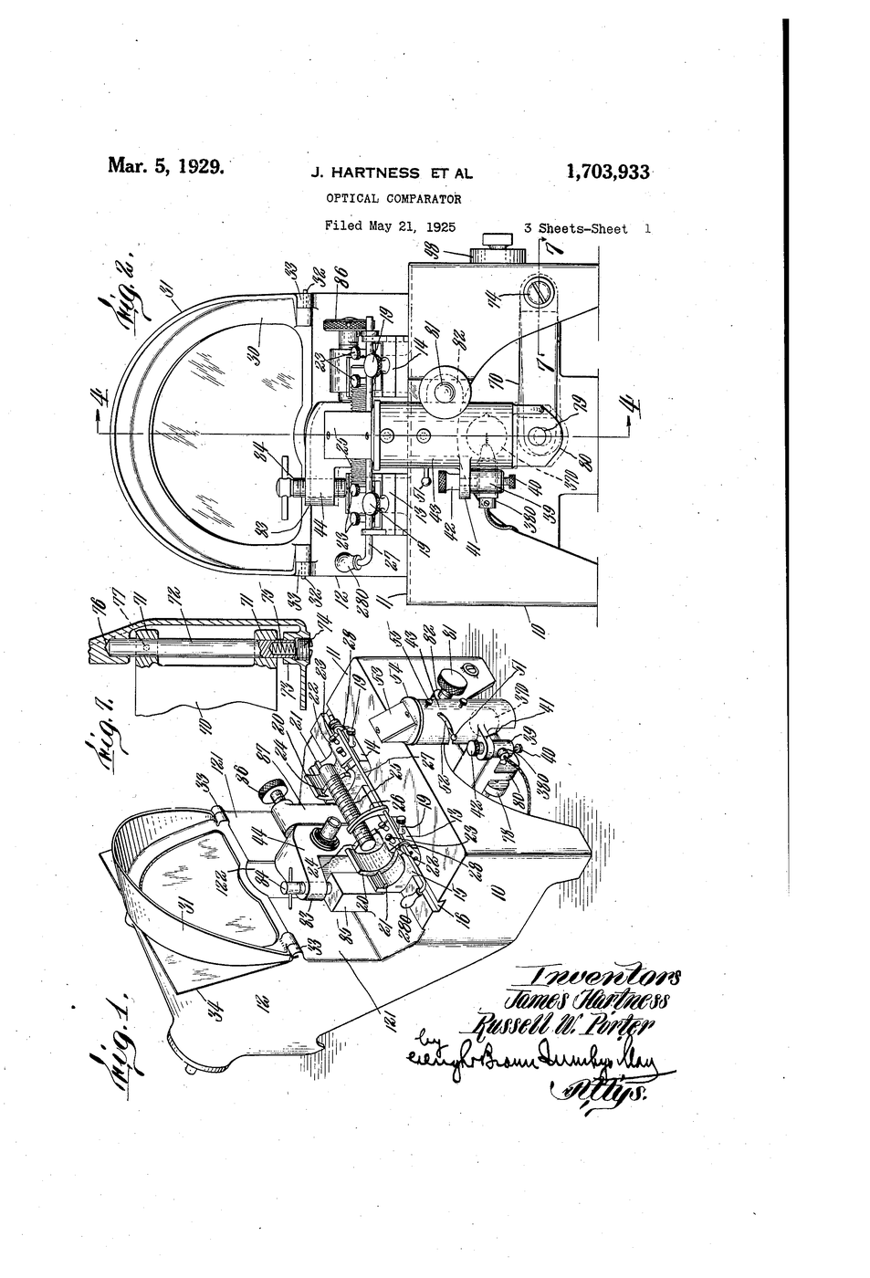
US 1,703,933, “Optical Comparator”, James Hartness and Russell W. Porter of Springfield, Vermont, filed 21 May 1925 and granted 5 March 1929. The instrument throws a hugely magnified shadow of the part onto a screen, where it is compared against a drawn master outline. Instead of measuring, you look at whether the shadow fits between two lines.
It converts a hard metrology problem into an easy visual one — the last and cleverest version of this batch's recurring theme: take the judgement away from the operator.
Інструкції
Read the claim before you build
Read the claim before you build
Hartness and Porter claim comparison of a projected profile against a master outline. Write down why a caliper cannot check the angle of a thread flank.
Try to measure a screw thread by touch
Try to measure a screw thread by touch
Attempt to measure the flank angle of a #6-32 screw with the caliper. Note how badly it goes.
Матеріали для цього кроку:
 #6-32 Machine Screw1 штука
Необхідні інструменти ({count})
 Vernier Caliper
Cast a shadow
Cast a shadow
In a darkened room, hold the screw in a narrow beam of light so its shadow falls on white paper on the wall.
Матеріали для цього кроку:
#6-32 Machine Screw1 штука Graph Paper1 аркуш
Change the magnification
Change the magnification
Move the screw closer to the light. The shadow grows. Magnification costs nothing but distance.
Матеріали для цього кроку:
#6-32 Machine Screw1 штукаMeasure the magnification factor
Measure the magnification factor
Measure the real screw diameter with the caliper and the shadow with the ruler. The ratio is your magnification. Write it down — an unknown magnification makes the shadow useless.
Матеріали для цього кроку:
Graph Paper1 аркушНеобхідні інструменти ({count})
Vernier Caliper Steel Ruler (30cm)
Sharpen the shadow
Sharpen the shadow
Make the light source smaller by masking it with foil pierced by a small hole. The shadow edge sharpens because a point source casts no penumbra.
Матеріали для цього кроку:
 Aluminium Foil1 аркуш
Необхідні інструменти ({count})
 Craft Knife
Fold the light path with a mirror
Fold the light path with a mirror
Bounce the beam off the acrylic mirror to lengthen the path without lengthening the bench. Hartness and Porter did exactly this to keep the instrument compact.
Необхідні інструменти ({count})
 Acrylic Mirror Sheet
Draw the master outline
Draw the master outline
On graph paper draw the correct thread profile at your magnification: 60° included angle for a standard thread. Use the protractor.
Матеріали для цього кроку:
Graph Paper1 аркушНеобхідні інструменти ({count})
 Protractor
 Permanent Marker
Add tolerance lines
Add tolerance lines
Draw a second outline slightly outside the first. The gap between them is the tolerance band, drawn rather than calculated.
Матеріали для цього кроку:
Graph Paper1 аркушНеобхідні інструменти ({count})
ProtractorCompare shadow to chart
Compare shadow to chart
Project the screw onto the chart. If the shadow stays between the lines, the part is good. No number was read and no judgement was made.
Матеріали для цього кроку:
#6-32 Machine Screw1 штукаMeasure the flank angle off the shadow
Measure the flank angle off the shadow
Now measure the angle directly on the enlarged shadow with the protractor. Trying this on the metal part is what step 2 showed to be impossible.
Необхідні інструменти ({count})
ProtractorInspect a damaged thread
Inspect a damaged thread
Deliberately blunt one screw's thread, project it, and compare with a good one. Damage invisible in the hand is obvious on the screen.
Матеріали для цього кроку:
#6-32 Machine Screw2 штукCheck a drill point profile
Check a drill point profile
Project a drill bit and measure its point angle from the shadow. Compare with the 118° you measured directly in the twist drill blueprint.
Необхідні інструменти ({count})
 Drill Bit SetProtractor
History & Context
History & Context
US 1,703,933, “Optical Comparator”, James Hartness and Russell W. Porter of Springfield, Vermont, filed 21 May 1925, granted 5 March 1929. It was made by the Jones & Lamson Machine Company and remained profitable for decades.
Two remarkable men. Hartness was a machine-tool designer with well over a hundred patents, president of the American Society of Mechanical Engineers, an early aviator, and Governor of Vermont from 1921 to 1923. Russell W. Porter is usually remembered under a completely different heading — as an Arctic explorer and the founder of the amateur telescope-making movement at Stellafane, and later as the illustrator of the 200-inch Palomar telescope. He is a named co-inventor on this patent, which is often overlooked.
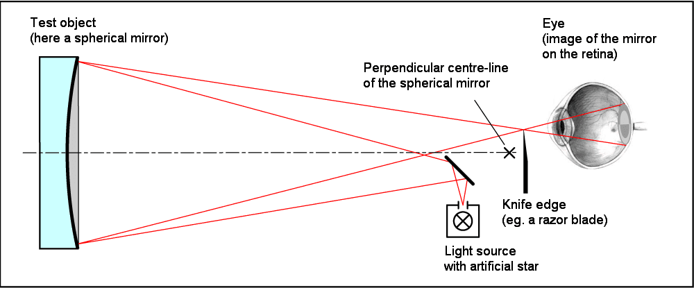
Why the same skills. Porter's telescope work and this comparator are the same discipline: getting light to carry a shape accurately from one place to another. The lens grinding and Foucault knife-edge blueprints linked here are the astronomical branch of the same craft — and the knife-edge test, like the comparator, works by turning an invisible error into a visible pattern.
The idea that ends this batch. Palmer made the thousandth readable. Starrett made it reproducible. Johansson made it a physical standard. Norton made it manufacturable. Hartness and Porter made it visible — and once an error is visible on a screen, checking it needs no metrologist at all. That is the whole century of this batch in one sentence.
Матеріали
3- 6 штукЗаповнювач
- 1 аркушЗаповнювач
- 1 аркушЗаповнювач
Необхідні інструменти
7- Заповнювач
- Заповнювач
- Заповнювач
- Заповнювач
- Заповнювач
- Заповнювач
- Заповнювач
Матеріали з пов'язаних креслень

Пов'язані креслення
Ці креслення діляться знаннями — техніки, матеріали або принципи


CC0 Суспільне надбання
Це креслення випущено під ліцензією CC0. Ви можете вільно копіювати, змінювати, поширювати та використовувати цю роботу для будь-яких цілей без запиту дозволу.
Підтримайте мейкера, купуючи продукти через його креслення, де він отримує Комісію мейкера встановлену вендорами, або створіть нову ітерацію цього креслення та включіть його як зв'язок у власне креслення для розподілу доходу.