
Співпраця
МИСТЕЦТВО
КРАСА ТА ЗДОРОВ'Я
РЕМЕСЛО
КУЛЬТУРА ТА ІСТОРІЯ
РОЗВАГИ
СЕРЕДОВИЩЕ
ЇЖА ТА НАПІЇ
ЗБОРНА ІНЖЕНЕРІЯ
НАУК
СПОРТ
ТЕХНОЛОГІЯ
НОСИМО
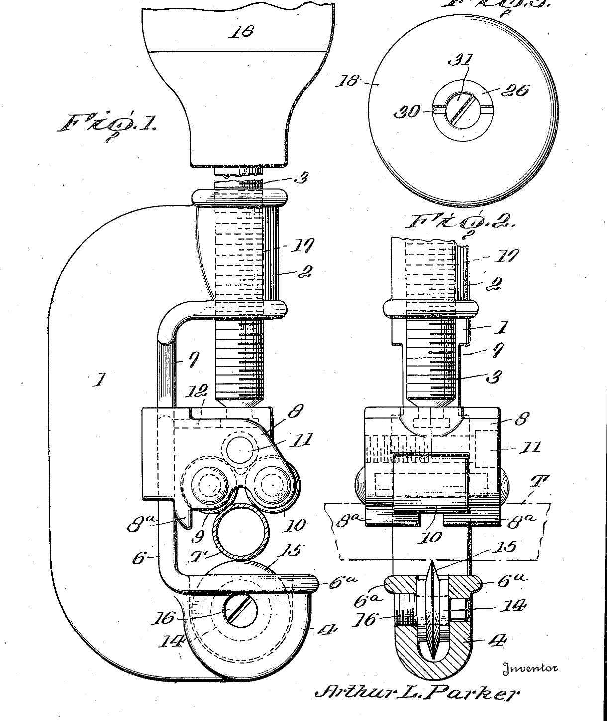
Slip-Knob Tube Cutter: the Feed Knob Turns the Screw Through Spring-Loaded Plates and Slips Before the Tube Is Crushed (Parker, 1944)
Forge

Створено

Forge

13. листопад 2026NO
7
0
0
0
0

Slip-Knob Tube Cutter: the Feed Knob Turns the Screw Through Spring-Loaded Plates and Slips Before the Tube Is Crushed (Parker, 1944)

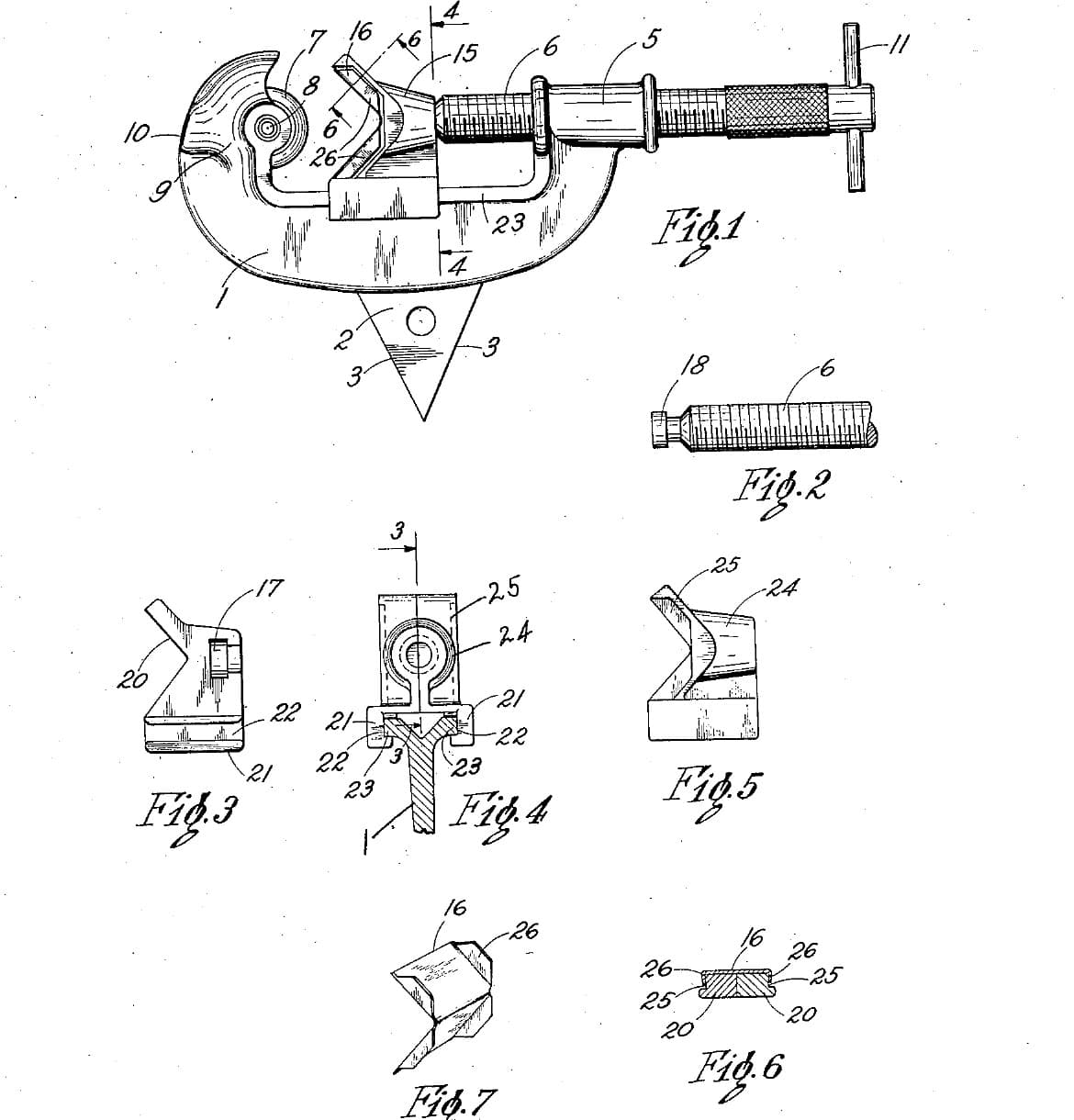
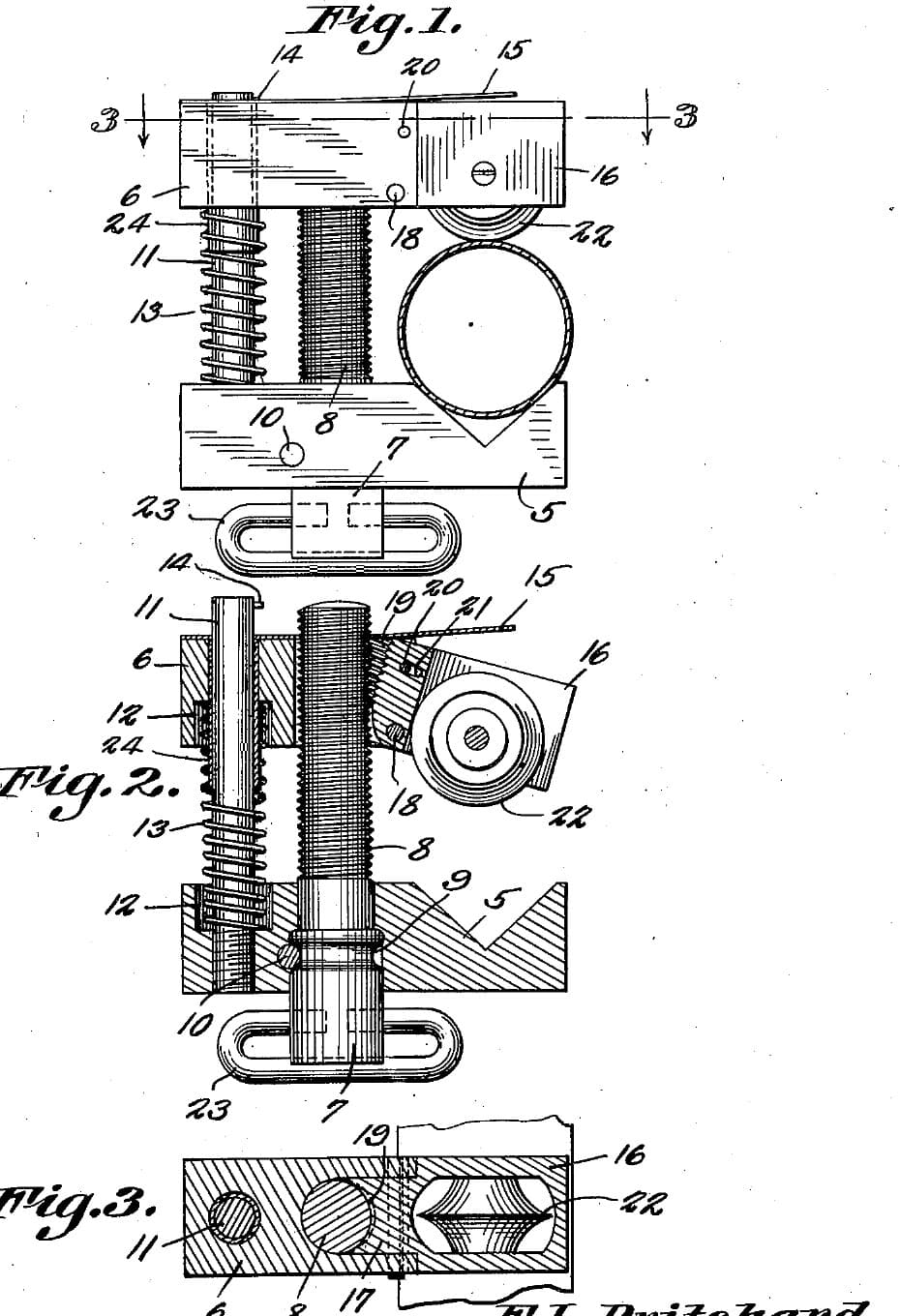
Arthur L. Parker of Cleveland, Ohio, received US 2,360,887, dated 24 October 1944 and assigned to The Parker Appliance Company, for a tube cutter that cannot be overfed. A one-piece frame holds the wheel at one end and the feed screw at the other. The screw pushes a carrier with two rollers, which press the tube onto the wheel. The screw is turned through a knob that slips when the turning force passes a set limit. Inside the knob, a brass plate on the screw is squeezed by a spring between two steel plates locked to the knob, and the spring can be set harder or softer. We saw the frame and carrier from steel plate and print the knob in PETG. His knob was moulded plastic. All sizes are ours.
Просунутий
About 4 days

Інструкції

1

Carrier height and slip torque

Завантаження блокнота Jupyter…
2

Read US 2,360,887

"If the operator exerts a pressure beyond a predetermined torque pressure, then the steel plates will slip on the brass plate and will not turn the feed screw."
3

Print the template

Frame, carrier half, rollers and wheel at 1:1, set for a 15 mm tube, with the screw, plates and sleeve sizes. print at 100 % (check the 50 mm bar).
Файл дизайнуPDFCC0 - Free
4

Saw out the frame

Glue the frame outline on 16 mm plate, drill a row of holes inside the C, saw to them and file to the line. Saw the 7 mm wheel slot down into the bottom arm with two cuts and file it flat. Drill 5 mm across it for the axle and tap the far cheek M5. Drill 8.5 mm down through the top arm and tap it M10. File the back bar to 8 mm thick over the short cut-away just under the top arm.

Матеріали для цього кроку:

Лист маловуглецевої сталіЛист маловуглецевої сталі1 штука

Необхідні інструменти ({count})
Ножівка по металуНожівка по металу
Набір напилківНабір напилків
Свердлильний верстатСвердлильний верстат
Машинні лещатаМашинні лещата
Набір сверделНабір свердел
Набір мітчиків і плашокНабір мітчиків і плашок
КернерКернер
РисувалкаРисувалка
Слюсарні лещатаСлюсарні лещата
Мастильно-охолоджувальна оливаМастильно-охолоджувальна олива
5

Make the carrier

Saw two carrier halves from 10 mm plate, one the mirror of the other. In each half's inner face, saw and file the channel for the back bar, the 6.25 mm deep recess for the rollers, and half of the T-slot for the screw head, open to the right. Leave the lips at the back and the two lugs at the bottom. Clamp the halves together and drill the two roller pin holes and the M5 bolt hole through both.

Матеріали для цього кроку:

Лист маловуглецевої сталіЛист маловуглецевої сталі1 штука

Необхідні інструменти ({count})

Ножівка по металуНожівка по металу
Набір напилківНабір напилків
Набір надфілівНабір надфілів
Свердлильний верстатСвердлильний верстат
Машинні лещатаМашинні лещата
Набір сверделНабір свердел
Слюсарні лещатаСлюсарні лещата
Цифровий штангенциркуль 6 дюймівЦифровий штангенциркуль 6 дюймів
6

Turn the rollers, screw and sleeve

From mild steel bar: turn two rollers 12 mm across and 12 mm long, bored 5 mm. Turn the feed screw from 16 mm bar: a 14 mm head 4 mm long, a 7 mm neck 4 mm long, then 102 mm at 10 mm, cut M10 with the die. File the top 12 mm to two flats 8 mm apart, and drill and tap its end M5, 15 mm deep. Turn the sleeve from 20 mm bar: an 18 mm flange 2 mm thick on a body 21 mm long cut M12, bored 5.5 mm, and saw two slots across the flange.

Матеріали для цього кроку:

Круглий пруток з маловуглецевої сталіКруглий пруток з маловуглецевої сталі2 штук

Необхідні інструменти ({count})
Токарний верстат по металуТокарний верстат по металу
Трикулачковий токарний патронТрикулачковий токарний патрон
Токарний різецьТокарний різець
Відрізний різецьВідрізний різець
Набір центрувальних сверделНабір центрувальних свердел
Набір сверделНабір свердел
Набір мітчиків і плашокНабір мітчиків і плашок
Набір напилківНабір напилків
Ножівка по металуНожівка по металу
Цифровий штангенциркуль 6 дюймівЦифровий штангенциркуль 6 дюймів
Мастильно-охолоджувальна оливаМастильно-охолоджувальна олива
7

Turn the cutting wheel

Chuck a tool steel bar and face it. Turn the end to 20 mm across for 10 mm, centre drill and drill a 5 mm hole 10 mm deep, and turn the edge to a 50 degree vee, 25 degrees each side, sharp in the middle of the 6 mm width. Part it off 6 mm long and take the burr off the hole.

Матеріали для цього кроку:

Пруток інструментальної сталіПруток інструментальної сталі1 штука

Необхідні інструменти ({count})

Токарний верстат по металуТокарний верстат по металу
Трикулачковий токарний патронТрикулачковий токарний патрон
Токарний різецьТокарний різець
Відрізний різецьВідрізний різець
Набір центрувальних сверделНабір центрувальних свердел
Набір сверделНабір свердел
Цифровий штангенциркуль 6 дюймівЦифровий штангенциркуль 6 дюймів
Захисні окуляриЗахисні окуляри
8

Harden and temper

Heat the wheel to a cherry red, until a magnet no longer sticks, and quench it in water, moving it about. Rub it bright with a stone, warm it on a piece of steel plate over the fire, and quench again as soon as it turns a light straw colour.

Необхідні інструменти ({count})

ГорноГорно
Ковальські кліщіКовальські кліщі
Невеликий магнітНевеликий магніт
Гартівна діжкаГартівна діжка
ВодаВода
Точильний каміньТочильний камінь
Зварювальні рукавиціЗварювальні рукавиці
Захисні окуляриЗахисні окуляри
9

Cut the clutch plates

Cut two 30 mm discs from 1.5 mm steel strip, each with two lugs 3.5 mm wide standing out 3 mm on opposite sides, and drill them 10.5 mm. Cut a 28 mm disc from 2 mm brass sheet and file its centre hole to slide snugly on the screw's flats. Make the faces flat on abrasive paper on a flat board.

Матеріали для цього кроку:

Смуга пружинної сталіСмуга пружинної сталі1 штука
Латунний листЛатунний лист1 штука

Необхідні інструменти ({count})

Ножівка по металуНожівка по металу
Набір напилківНабір напилків
Набір надфілівНабір надфілів
Свердлильний верстатСвердлильний верстат
Набір сверделНабір свердел
Слюсарні лещатаСлюсарні лещата
Цифровий штангенциркуль 6 дюймівЦифровий штангенциркуль 6 дюймів
10

Print the knob's lower section

Floor with a 10.5 mm hole for the screw, the 31 mm chamber with two grooves for the plates' lugs, three holes for M4 screws. Print it floor down in PETG, 0.2 mm layers, 5 walls, 40 % infill.
Файл дизайнуSTLCC0 - Free
11

Print the knob's upper section

The hex channel for the M12 nut (the collar) and the sleeve's flange, which stops under the top wall, and a 15 mm hole to reach its slots. Print it top down in PETG, 0.2 mm layers, 5 walls, 40 % infill.
Файл дизайнуSTLCC0 - Free
12

Assemble the frame and carrier

Put the wheel in its slot on the M5 cap screw. Screw the feed screw down through the top arm. Lay the rollers on their pins in one carrier half, slide the half onto the back bar from the cut-away with the screw head in its slot, close the other half over it and bolt them together. Run the carrier down: its lugs should land on the bottom arm with the rollers clear of the wheel.

Матеріали для цього кроку:

Сталевий штифтСталевий штифт2 штук
Гвинт із циліндричною головкою та внутрішнім шестигранникомГвинт із циліндричною головкою та внутрішнім шестигранником2 штук
Шестигранна гайкаШестигранна гайка1 штука

Необхідні інструменти ({count})
Набір шестигранних ключівНабір шестигранних ключів
Розвідний ключРозвідний ключ
Мастильно-охолоджувальна оливаМастильно-охолоджувальна олива
13

Fit the slip knob

Slide the lower section over the screw's top. Drop in a steel plate, lugs in the grooves, then the brass disc on the flats, then the second steel plate. Stand the spring on it. Push the sleeve, flange first, up into the upper section's hex channel until it stops under the top wall. Push the M12 nut in under it and turn the sleeve from the top with a screwdriver to draw the nut on a few turns. Screw the two sections together with three M4 screws. Put an M5 bolt down through the sleeve into the screw and tighten it.

Матеріали для цього кроку:

Набір пружин стискуНабір пружин стиску1 штука
Шестигранна гайкаШестигранна гайка1 штука
Гвинт із циліндричною головкою та внутрішнім шестигранникомГвинт із циліндричною головкою та внутрішнім шестигранником4 штук
Плоска шайбаПлоска шайба1 штука

Необхідні інструменти ({count})

Набір шестигранних ключівНабір шестигранних ключів
Розвідний ключРозвідний ключ
14

Set the slip

Put a tube in, turn the knob until the rollers grip it, and try a cut. If the knob slips before the wheel cuts, turn the sleeve with a screwdriver through the top hole so the nut moves down and squeezes the spring harder. If the tube starts to flatten before it slips, set it softer. Set it once for the tubes you cut most.

Необхідні інструменти ({count})

Набір шестигранних ключівНабір шестигранних ключів
15

Cut a copper tube

Mark a copper tube and hold it in a vice with soft jaws, or by hand for small tubes. Turn the knob until the rollers press the tube onto the wheel. Turn the cutter once round, give the screw about a quarter turn, and go on until the tube parts. The wheel should run in its own groove; the end should be square and not squeezed oval. Clean the inside of the end with a deburring tool.

Матеріали для цього кроку:

Мідна трубаМідна труба1 штука

Необхідні інструменти ({count})

Слюсарні лещатаСлюсарні лещата

Знімач задирокЗнімач задирок
Цифровий штангенциркуль 6 дюймівЦифровий штангенциркуль 6 дюймів
16

Troubleshooting

Slip-knob tube cutter troubleshooting.

Flow

Loading...
17

History and honest limits

**Arthur L. Parker** of Cleveland, Ohio, US 2,360,887, dated 24 October 1944, filed 21 December 1943, assigned to The Parker Appliance Company. He claimed "yieldable means connecting the knob to the feed screw for turning the same, said yieldable means being releasable to permit the knob to turn on the feed screw when a predetermined turning torque is applied". His knob sections were moulded plastic and screwed together, and his collar had lugs in the knob's grooves; ours are printed, held by three screws, and the collar is a hex nut in a hex channel. The patent gives no sizes or spring force; all of ours are ours, and the slip is set by test.

Матеріали

11

Необхідні інструменти

28

Файли дизайну

3

За цим кресленням виготовляють

CC0 Суспільне надбання

Це креслення випущено під ліцензією CC0. Ви можете вільно копіювати, змінювати, поширювати та використовувати цю роботу для будь-яких цілей без запиту дозволу.

Підтримайте мейкера, купуючи продукти через його креслення, де він отримує Комісію мейкера встановлену вендорами, або створіть нову ітерацію цього креслення та включіть його як зв'язок у власне креслення для розподілу доходу.

Обговорення

(0)

Увійти щоб приєднатися до обговорення

Завантаження коментарів...