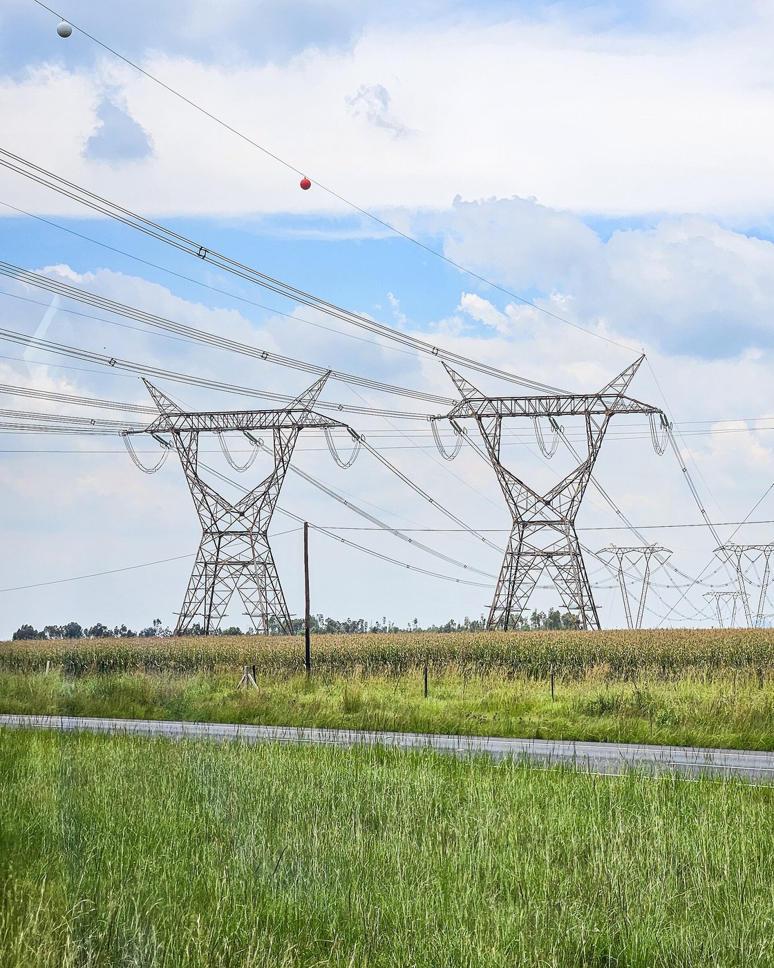
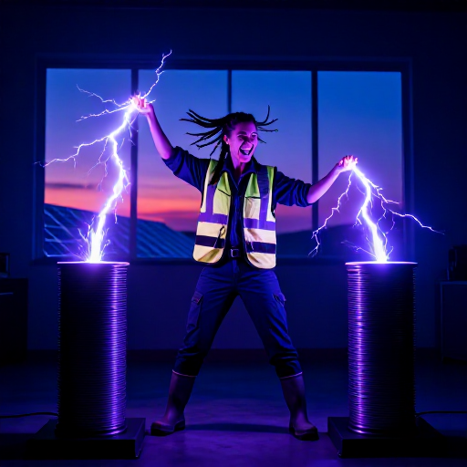

Three-Phase Transmission
Інструкції
Generate three phases and prove they sum to zero
Generate three phases and prove they sum to zero
The whole economic argument rests on one arithmetical fact — verify it.
- Build or simulate three sine sources of equal amplitude, spaced 120 degrees apart.
- Display all three on the oscilloscope together.
- Now sum all three electrically and display the result.
- Observe the sum with balanced loads on all three phases.
The sum is a flat line. At every instant, whatever one phase is doing, the other two are doing the opposite between them. So a neutral conductor joining three balanced loads carries no current at all — and a conductor carrying nothing can be left out. That is the entire saving, and it exists only while the three loads are balanced.
Unbalance one load and watch the sum come alive. Real distribution networks keep a neutral precisely because domestic loads are never balanced, while transmission lines omit it because the large loads they serve are.Матеріали для цього кроку:
 Набір резисторів 1/4 Вт1 набір
 Міліметровий папір1 pad
Необхідні інструменти ({count})
 DDS Signal Generator (1Hz-65MHz)
 Digital Oscilloscope (100MHz, 2-Channel)
 Digital Multimeter (Lab Grade)
Wire star and delta, and see what each gives you
Wire star and delta, and see what each gives you
Two ways to connect three phases, with different voltages and different uses.
- Connect three loads in STAR — one end of each to a common point, the other three to the lines.
- Measure line-to-line and line-to-neutral voltages and find their ratio.
- Now reconnect the same loads in DELTA — each load between two lines.
- Measure the current in a load and in a line, and find that ratio.
Star gives you two voltages from one supply — the higher between any two lines, the lower between any line and neutral — which is why domestic supplies are one phase and neutral of a three-phase system while industrial motors take all three. Delta has no neutral and is used where none is needed, and it keeps working with one winding failed, which star does not.
The ratio between the two star voltages is the square root of three, and it appears everywhere in three-phase work. It comes straight from the 120-degree geometry, not from any convention.Матеріали для цього кроку:
 Голий мідний дріт 10 AWG1 рулонНабір резисторів 1/4 Вт1 набір
Необхідні інструменти ({count})
Digital Multimeter (Lab Grade)Digital Oscilloscope (100MHz, 2-Channel) Analog Multimeter
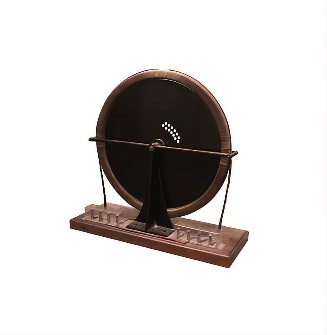
Make a rotating field with three coils
Make a rotating field with three coils
Three phases produce rotation directly, with nothing mechanical involved.
- Arrange three coils at 120 degrees around a circle.
- Feed each from one phase.
- Suspend a compass needle or a small aluminium disc at the centre.
- Watch it turn — and note which way.
- Now swap any two phase connections and watch again.
Матеріали для цього кроку:
 Мідний дріт в емалевій ізоляції1 рулон
 Набір феритових намистин1 набір
 Алюмінієва фольга1 рулон
Необхідні інструменти ({count})
Digital Multimeter (Lab Grade)Digital Oscilloscope (100MHz, 2-Channel) Digital Caliper 6-Inch
Compute the copper saving that decided the argument
Compute the copper saving that decided the argument
Put numbers on it, because the numbers are why AC won.
- Work out the conductor cross-section needed to deliver a given power single-phase over a given distance at a given loss.
- Work out the same for three-phase at the same line voltage.
- Compare total copper mass for both.
- Now double the voltage and recompute the single-phase case.
Матеріали для цього кроку:
Міліметровий папір1 padНеобхідні інструменти ({count})
Digital Multimeter (Lab Grade)Digital Caliper 6-InchLauffen to Frankfurt, and history
Lauffen to Frankfurt, and history
In 1891 a three-phase line carried power 175 km from a hydroelectric plant at Lauffen am Neckar to the International Electrotechnical Exhibition in Frankfurt, lighting a thousand lamps and driving a waterfall pump. Mikhail Dolivo-Dobrovolsky of AEG designed the three-phase generator, transformers and motor; Charles Brown of Oerlikon built much of the plant. It ran at about 75 per cent efficiency over that distance, which nobody had believed possible.
It ended the war of the currents as a practical matter. Edison's DC system could not transform voltage, so it needed a generating station every mile or so; the Frankfurt demonstration showed power being generated where the water was and used where the people were. Within a decade three-phase was the world standard for transmission, and it still is.
Three phases rather than two or four is a genuine optimum. Two phases work and were used briefly at Niagara, but need four wires and give a lumpier rotating field. More than three gives diminishing returns for more conductors. Three is the smallest number that produces a smooth rotating field and a zero-sum neutral, and that is why the whole world converged on it.
Its honest limits: the neutral-free saving holds only for balanced loads; long AC lines suffer reactive losses that grow with length and make very long links inefficient; and AC cannot easily join two grids running at different frequencies or out of step. All three limits are what the HVDC blueprint at the end of this batch addresses — sixty-three years later, using DC again.
Матеріали
6- 1 набірЗаповнювач
- 1 padЗаповнювач
- 1 рулонЗаповнювач
- Заповнювач
- 1 набірЗаповнювач
- 1 рулонЗаповнювач
Необхідні інструменти
5- Заповнювач
- Цифровий осцилограф10% комісіяMagento Legacy Storeships internationallyЗаповнювач
- Заповнювач
- Заповнювач
- Заповнювач
Пов'язані креслення
Ці креслення діляться знаннями — техніки, матеріали або принципи

CC0 Суспільне надбання
Це креслення випущено під ліцензією CC0. Ви можете вільно копіювати, змінювати, поширювати та використовувати цю роботу для будь-яких цілей без запиту дозволу.
Підтримайте мейкера, купуючи продукти через його креслення, де він отримує Комісію мейкера встановлену вендорами, або створіть нову ітерацію цього креслення та включіть його як зв'язок у власне креслення для розподілу доходу.