ART
BEAUTY & WELLNESS
CRAFT
CULTURE & HISTORY
ENTERTAINMENT
ENVIRONMENT
FOOD & DRINKS
REVERSE ENGINEERING
SCIENCES
SPORTS
TECHNOLOGY
WEARABLES
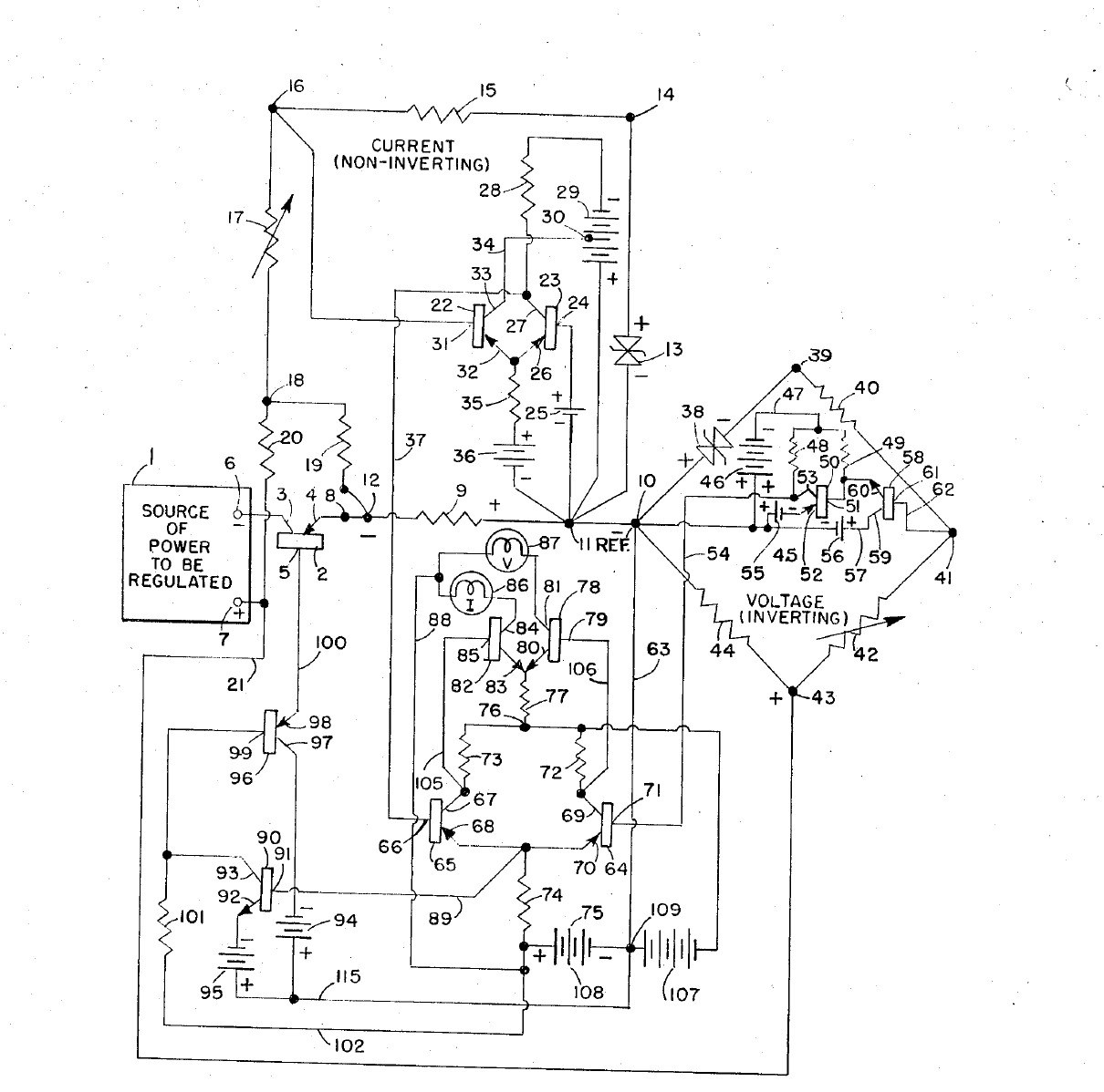


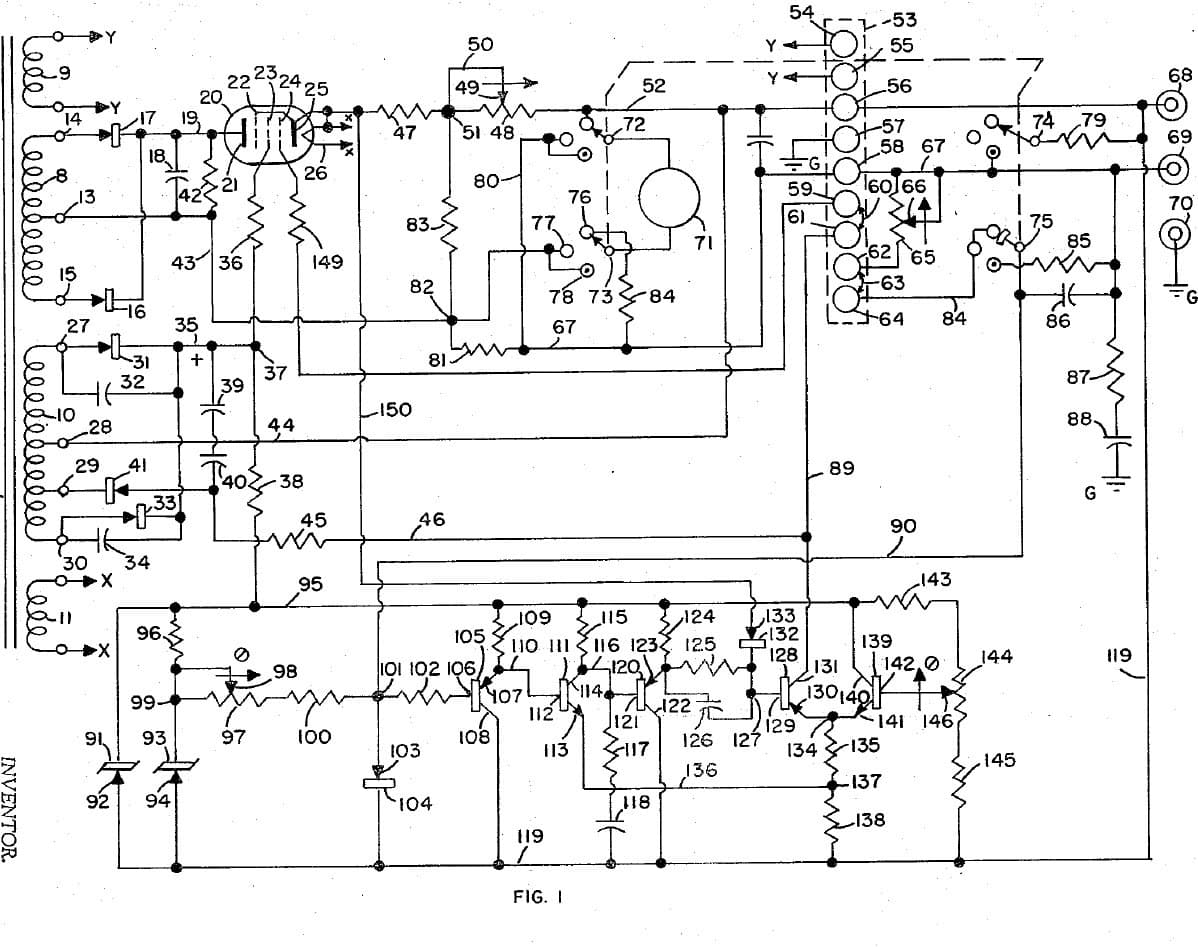
Adjustable Bench Power Supply: Constant Voltage / Constant Current with Cross-Over Lamps (Gately, Forbro, US 3,303,411, 1967)
An all-transistor bench supply with two knobs: one sets the voltage, the other the current. It holds the set voltage until the load tries to draw more than the set current, then switches at once to holding the current, and back again, with no in-between state. Two lamps show which mode is in control.
Result: an adjustable constant-voltage / constant-current DC supply with mode lamps.
Source: J. R. Gately (Forbro Design), US 3,303,411 (1967). Unknown: all component values and ratings. Builds on the same inventor's 1966 current-limited supply. Picture: the patent drawing.
Advanced
Unknown
Instructions
1
1
Build the raw supplies
Build the raw supplies
In a case, wire the cord through a switch and fuse to two power transformers, each with rectifiers and a filter: one gives the main power to be regulated, the other the bias supplies, held steady by Zener diodes. Not given: the voltages. Ours: the case, switch and fuse.
Materials for this step:
 Aluminium Enclosure Box1 piece
 Flexible Cord with Plug1 piece
 Toggle Switch1 piece
 Fuse1 piece
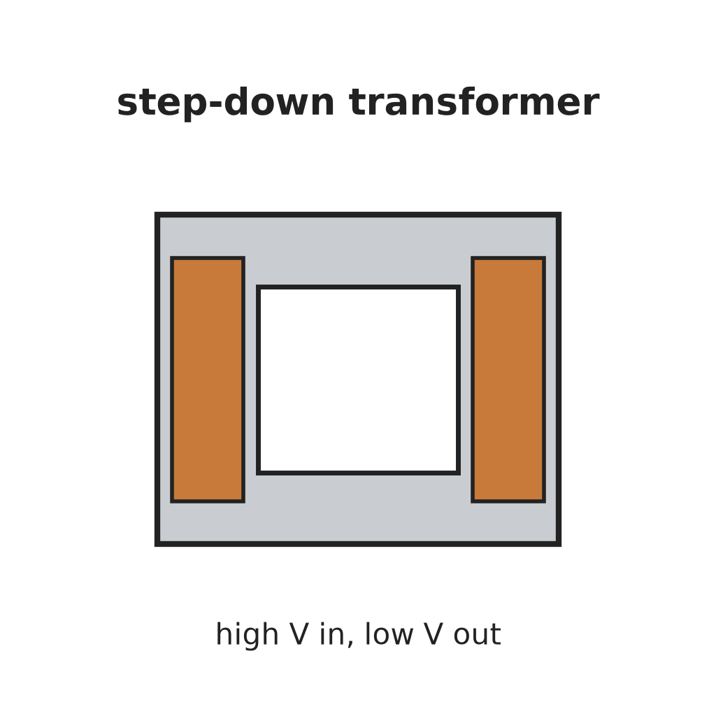 Step-Down Transformer2 pieces
 Diode6 rectifiers
 Electrolytic Capacitor3 filters
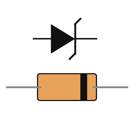 Zener Diode2 bias
Tools needed:
 Hand Drill
 Screwdriver Set
2
2
Fit the pass transistor and current bridge
Fit the pass transistor and current bridge
Put a power transistor on a heat sink in series with the output: collector to the negative supply, emitter through a current-sensing resistor to the negative output terminal. Make the current bridge from the sensing resistor, a reference Zener, a reference resistor and the adjustable current-control resistor: the output current is proportional to its setting. A small trimming resistor sets the maximum current. Not given: the values.
Materials for this step:
 Power Transistor1 series pass
 Heat Sink1 pieceZener Diode1 current reference
 Rheostat1 current control
 Resistor1 sensing, reference, trim set
 Binding Post2 output + and -
Tools needed:
 Soldering Iron
3
3
Build the voltage bridge
Build the voltage bridge
Make the voltage bridge from a reference Zener, a reference resistor, the adjustable voltage-control resistor and the load itself across the output. A small trimming resistor sets the maximum voltage. Add two resistors that feed the current bridge enough extra to cover the voltage bridge's own current and any voltmeter across the output, so low currents are still held exactly.
Materials for this step:
Zener Diode1 voltage referenceRheostat1 voltage controlResistor1 reference, trim, compensation setTools needed:
Soldering Iron4
4
Build the amplifiers and cross-over
Build the amplifiers and cross-over
Give each bridge an error amplifier. Feed the two amplified errors to the bases of a pair of transistors sharing one emitter resistor: whichever base is the more negative takes control and cuts the other off, so the supply is always cleanly in voltage mode or current mode. Amplify the shared emitter signal through two more transistors to drive the pass transistor's base. Add an emitter-follower clamp on the bias line. Not given: the transistor types.
Materials for this step:
 Printed Circuit Board1 piece
 Transistor Assortment1 error amplifiers, cross-over pair, drivers, clampResistor1 set
 Potentiometer1 clamp divider
 Solder Wire1 as needed
Tools needed:
Soldering Iron5
5
Fit the mode lamps and use it
Fit the mode lamps and use it
From the cross-over pair, drive two lamp transistors, each lighting one lamp: one for voltage mode, one for current mode. In use, set the voltage and the current limit. With a light load the voltage lamp is lit and the voltage holds; if the load tries to draw more than the set current, the supply switches to holding the current and the current lamp lights.
Materials for this step:
Transistor Assortment1 two lamp drivers Lamp Socket2 pieces
 Light Bulb2 pieces
Tools needed:
Screwdriver SetMaterials
19- 1 piecePlaceholder
- 1 piecePlaceholder
- Placeholder
- 1 piecePlaceholder
- 2 piecesPlaceholder
- 6 rectifiersPlaceholder
- 3 filtersPlaceholder
- 1 voltage referencePlaceholder
- 1 series passPlaceholder
- 1 piecePlaceholder
- 1 voltage controlPlaceholder
- 1 setPlaceholder
- Placeholder
- 1 piecePlaceholder
- 1 two lamp driversPlaceholder
- Placeholder
- 1 as neededPlaceholder
- 2 piecesPlaceholder
- 2 piecesPlaceholder
Tools Required
3- Placeholder
- Placeholder
- 2 vendors sell this, none ship to you yetPlaceholder
This blueprint makes

Related Blueprints
These blueprints share knowledge with this one — techniques, materials, or principles that connect them in the learning graph.
CC0 Public Domain
This blueprint is released under CC0. You are free to copy, modify, distribute, and use this work for any purpose, without asking permission.
Support the Maker by purchasing products through their Blueprint where they earn a Maker Commission set by Vendors, or create a new iteration of this Blueprint and include it as a connection in your own Blueprint to share revenue.