ART
BEAUTY & WELLNESS
CRAFT
CULTURE & HISTORY
ENTERTAINMENT
ENVIRONMENT
FOOD & DRINKS
REVERSE ENGINEERING
SCIENCES
SPORTS
TECHNOLOGY
WEARABLES
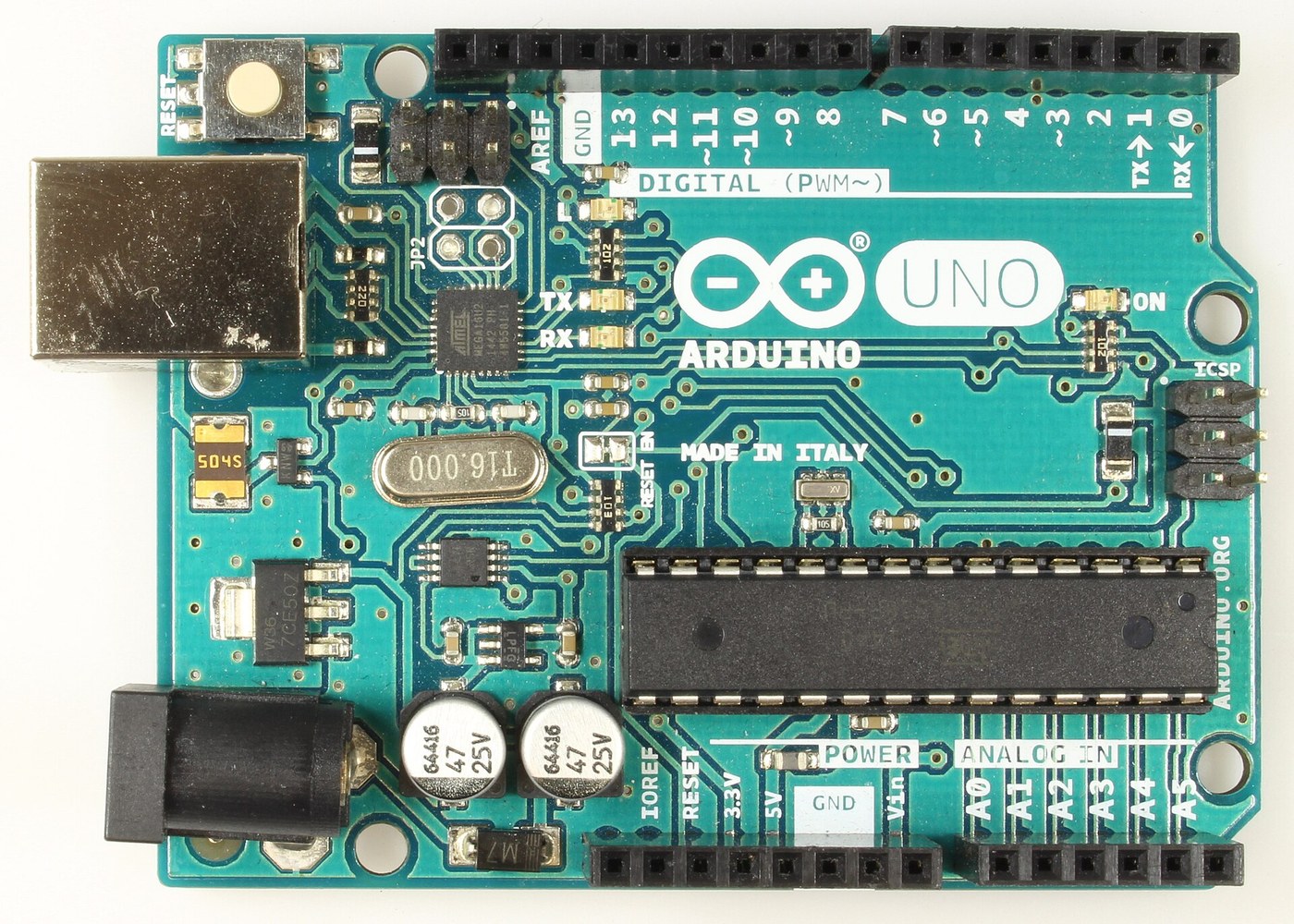


Arduino Uno R3: Assembled from Arduino's Open UNO-TH Rev3e Design Files and Flashed over ICSP
The Arduino Uno R3 is open hardware: Arduino publishes its schematic and board layout. This blueprint builds one from those files, part by part, then loads the firmware into its two processors.
Result: an Arduino Uno R3. An ATmega328P (16 MHz, 32 kB flash, 2 kB SRAM, 1 kB EEPROM) runs your programs; an ATmega16U2 turns USB into its serial link. It runs from USB (5.5 V at most) or 6-20 V at the DC jack.
Source: Arduino UNO-TH_Rev3e design files and the A000066 schematic and datasheet (Arduino, CC BY-SA). Unknown: how every bought part is made; no public source in hand says. The soldering method is ours. Picture: Wikimedia Commons.
Advanced
1 day
Instructions
1
1
Get the bare board
Get the bare board
Have the two-layer board made to Arduino's UNO-TH_Rev3e board layout (the .brd file of the design files). Check it against the schematic before fitting anything.
Materials for this step:
 Printed Circuit Board1 UNO-TH Rev3e layout
Tools needed:
 Magnifying Loupe
2
2
Fit the small surface-mount parts
Fit the small surface-mount parts
Solder the chip parts to their marked places: resistor arrays RN1 (10K), RN2 and RN4 (1K), RN3 (22R); R1, R2 (1M); capacitors C1, C2, C4-C7, C10 (100n), C3, C8 (1u), C9, C11 (22p); varistors Z1, Z2; ferrite bead L1; inductor L2 (10 uH); diodes D2, D3; LEDs ON (green), L, RX, TX (yellow). Ours: flux, tweezers and hot air or a fine iron, checked under a loupe.
Materials for this step:
 Chip Resistor Array4 RN1-RN4
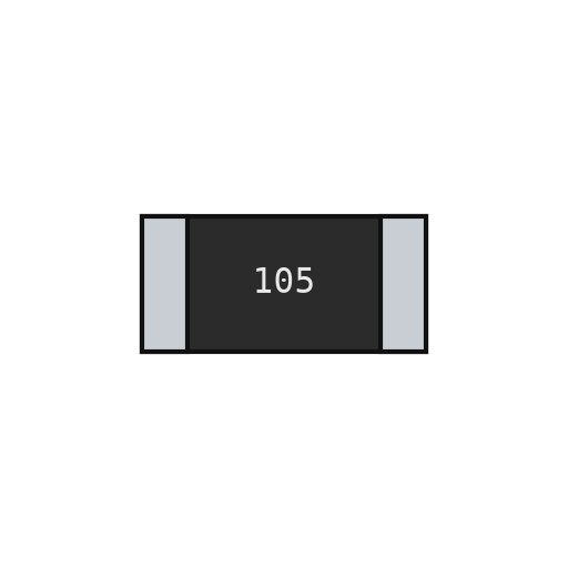 Chip Resistor2 1M
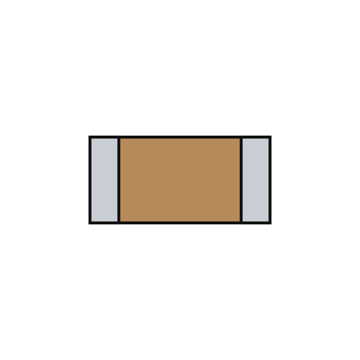 Ceramic Chip Capacitor11 7x100n, 2x1u, 2x22p
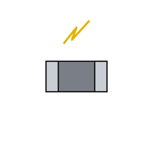 Chip Varistor2 Z1, Z2
 Ferrite Bead1 L1
 Surface-Mount Inductor1 L2
 Surface-Mount Diode2 D2, D3
 Chip LED4 1 green, 3 yellow
 Solder Wire1 a little
Tools needed:
 Flux
 Fine-Tip Tweezers
 Hot Air Rework Station
 Soldering IronMagnifying Loupe
3
3
Fit the power and chip parts
Fit the power and chip parts
Solder the ATmega16U2 (U3), the 16 MHz resonator Y2 and crystal Y1, the 5 V regulator NCP1117 (U1) and 3.3 V regulator LP2985 (U2), the LMV358 op-amp (U5), the FDN340P transistor (T1), the M7 diode (D1), the 500 mA resettable fuse (F1) and the 47 uF capacitors PC1, PC2 with their polarity as marked.
Materials for this step:
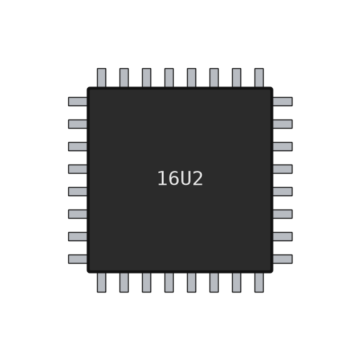 ATmega16U2 Microcontroller1 U3
 Piezoelectric Ceramic Resonator1 Y2
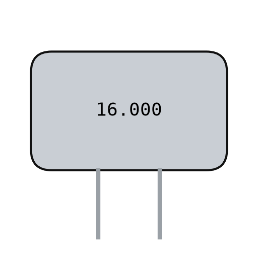 Quartz Crystal1 Y1
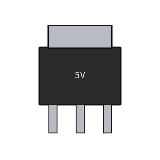 Linear Voltage Regulator2 U1 5 V, U2 3.3 V
 Op-Amp IC1 U5 LMV358
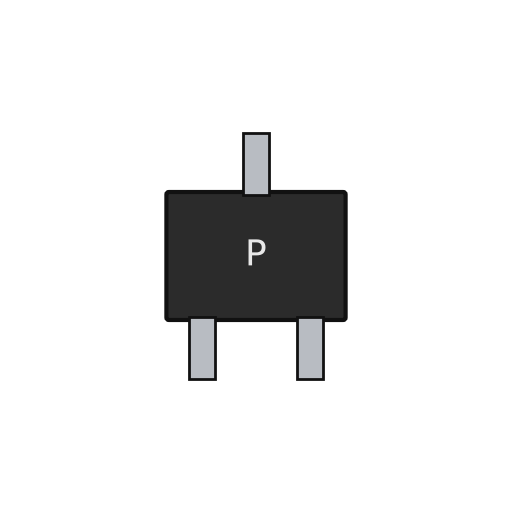 P-Channel MOSFET1 T1Surface-Mount Diode1 D1 M7
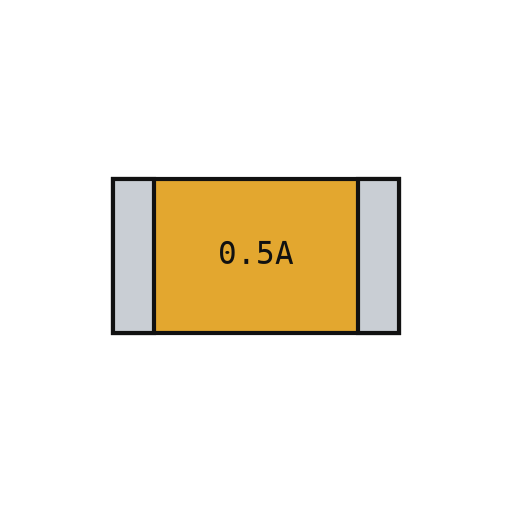 Resettable Fuse1 F1
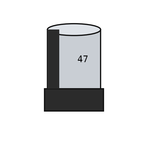 Polarised Chip Capacitor2 PC1, PC2Solder Wire1 a little
Tools needed:
FluxFine-Tip TweezersHot Air Rework StationSoldering IronMagnifying Loupe4
4
Fit the through-hole parts
Fit the through-hole parts
Solder the USB-B socket (X2), the DC jack (X1), the reset switch, the female headers (one 10-way, two 8-way, one 6-way) and the two 2x3 ICSP headers. Seat the ATmega328P in its place (ZU4).
Materials for this step:
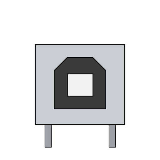 USB-B Socket1 X2
 DC Barrel Jack1 X1
 Push Button1 RESET
 Pin Header6 10x1, 2x 8x1, 6x1 female; 2x 3x2 ICSP
 ATmega328P Microcontroller1 ZU4Solder Wire1 as needed
Tools needed:
Soldering Iron5
5
Flash and check
Flash and check
Check with a meter that 5 V and GND are not shorted. Through the ICSP headers, load the USB-to-serial firmware into the ATmega16U2 and the bootloader into the ATmega328P. Plug in USB: the green ON LED lights, and the blink test in the next step flashes the L LED. Ours: an AVR ISP programmer and a multimeter.
Materials for this step:
 Arduino Uno Firmware1 download
Tools needed:
 Multimeter
 AVR ISP Programmer
 USB-B Cable
6
6
The blink test
The blink test
blink_test.ino: the same check as Arduino's Blink example. Upload it over USB from the Arduino IDE with the board set to Arduino Uno; the L LED on pin 13 turns on for one second and off for one second, over and over. If it does, both processors, the USB link and the bootloader work.
blink_test.inocpp
Tools needed:
USB-B CableMaterials
24- 1 UNO-TH Rev3e layoutPlaceholder
- 4 RN1-RN4Placeholder
- 2 1MPlaceholder
- 11 7x100n, 2x1u, 2x22pPlaceholder
- 2 Z1, Z2Placeholder
- 1 L1Placeholder
- Placeholder
- 1 D1 M7Placeholder
- 4 1 green, 3 yellowPlaceholder
- 1 as neededPlaceholder
- Placeholder
- Placeholder
- 1 Y1Placeholder
- 2 U1 5 V, U2 3.3 VPlaceholder
- 1 U5 LMV358Placeholder
- 1 T1Placeholder
- 1 F1Placeholder
- 2 PC1, PC2Placeholder
- 1 X2Placeholder
- Placeholder
- Placeholder
- Placeholder
- Placeholder
- 1 downloadPlaceholder
Tools Required
8- Placeholder
- Placeholder
- Placeholder
- Placeholder
- 2 vendors sell this, none ship to you yetPlaceholder
- Placeholder
- Placeholder
- 1 vendor sell this, none ship to you yetPlaceholder
This blueprint makes
Related Blueprints
These blueprints share knowledge with this one — techniques, materials, or principles that connect them in the learning graph.
CC0 Public Domain
This blueprint is released under CC0. You are free to copy, modify, distribute, and use this work for any purpose, without asking permission.
Support the Maker by purchasing products through their Blueprint where they earn a Maker Commission set by Vendors, or create a new iteration of this Blueprint and include it as a connection in your own Blueprint to share revenue.