Collaboration
ART
BEAUTY & WELLNESS
CRAFT
CULTURE & HISTORY
ENTERTAINMENT
ENVIRONMENT
FOOD & DRINKS
REVERSE ENGINEERING
SCIENCES
SPORTS
TECHNOLOGY
WEARABLES
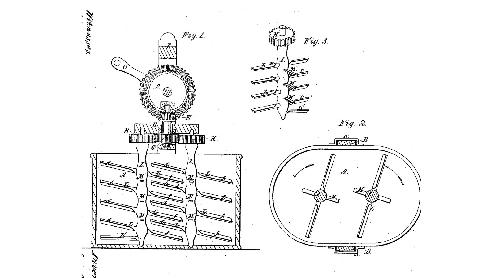

Twin Inclined-Wing Dasher Churn: Two Geared Dashers With Up- and Down-Sloping Wings Turn Through Each Other, Flat Wings Between
Levi Bissell of North Bergen, New York, received US 29,052, dated 10 July 1860, for a churn with two upright dashers in an oblong body. A crank on a lift-off frame drives both through gears, the same way round, so their wings pass each other in opposite directions in the middle. Each dasher's wings slope up on one side and down on the other, and one dasher's down-sloping wings pass between the other's up-sloping ones, so the cream is driven up and down at once. Flat wings between them check the swirl.
The patent gives no sizes; every size here is ours.
Intermediate
About 3 days
Instructions
1
1
Where the wings meet
Where the wings meet
Loading Jupyter Notebook...
2
2
Two shafts turned the same way by one wheel, eight months before
Two shafts turned the same way by one wheel, eight months before
Cornell's two shafts also turn the same way off one wheel, lying flat. Bissell stands them upright and slopes the wings.
3
3
Read US 29,052
Read US 29,052
"Thus it will be seen that the downwardly inclined wings move in paths describing broad cones, pointing upward; while the upwardly inclined wings describe cones pointing downward; and as these rapidly alternate, they cut paths through the milk or cream rapidly crossing each other, thereby producing intense and effective agitation of the cream."
4
4
Body A and sockets a
Body A and sockets a
Draw two 330 mm circles, centres 220 mm apart, joined by straight lines, on 20 mm hardwood glued up wide enough, and cut the floor to it. Rout a groove 1.6 mm wide and 8 mm deep on the 290 mm circles and their joining lines. Cut two strips of 1.5 mm stainless sheet 428 mm high, bend them to the outline, stand them in the groove with silicone sealant, and lap and rivet the joins on the straight sides with sealant between. Glue up a hardwood rim 18 mm thick and 30 mm deep to fit round the top, screwed through the sheet. Screw a hardwood block 60 x 64 x 70 mm to the middle of each long side, 150 mm up, with a 24 mm square socket a down through it, sealing the screw holes.
Materials for this step:
 Hardwood Board3 pieces
 Stainless Steel Sheet2 pieces
 Silicone Sealant1 piece
 Pop Rivets12 pieces
 Wood Glue1 piece
 Wood Screws24 pieces
Tools needed:
 Compass
 Jigsaw
 Router
 Chisel Set - Wood
 Tin Snips
 Pop Rivet Gun Kit
 Cordless Drill
 Drill Bit Set
 Bar Clamp
 Screwdriver Set
5
5
Dashers I with wings L and M
Dashers I with wings L and M
Cut two hardwood shafts 28 mm round and 408 mm long; turn the foot of each to 16 mm for 18 mm, and set a 16 mm stainless rod 103 mm long 40 mm into the top, pinned. Cut eight hardwood wings L 250 x 25 x 8 mm and six flat wings M 114 x 24 x 8 mm. Chisel slots through each shaft and drive the wings through, each pinned with a small dowel: the L pairs sloping 20 degrees, all in one plane, at 60, 140, 220 and 300 mm above the floor on one shaft and 100, 180, 260 and 340 mm on the other; the M wings flat, at right angles to the L, midway between them. Screw two hardwood steps 40 mm across, each with a 16.6 mm hole 6 mm deep, to the floor at the two end centres.
Materials for this step:
Hardwood Board1 piece Stainless Steel Rod1 piece
 Hardwood Dowels1 pieceWood Glue1 pieceWood Screws4 pieces
Tools needed:
 Table SawChisel Set - WoodCordless DrillDrill Bit Set
 Hacksaw
 Files (Hand File)
 Bench Vise
6
6
Print the cog-wheel G
Print the cog-wheel G
The cog-wheel G on the upright shaft: 40 teeth, module 2.75, 12 mm thick, 12.4 mm bore. PETG, 0.2 mm layers, 30 % infill, 4 walls.
7
7
Print the pinions H (two)
Print the pinions H (two)
The two pinions H on the dasher shafts, the same size as G: 40 teeth, module 2.75, 16.4 mm bore. Print two. PETG, 0.2 mm layers, 30 % infill, 4 walls.
8
8
Print the crown wheel D
Print the crown wheel D
The driving wheel D on the crank shaft, a crown wheel of 36 teeth, module 2, 12.4 mm bore. PETG, 0.2 mm layers, 30 % infill, 4 walls.
9
9
Print the pinion E
Print the pinion E
The pinion E on the upright shaft, 12 teeth, module 2, 12.4 mm bore, meshing the crown wheel D. PETG, 0.2 mm layers, 30 % infill, 4 walls.
10
10
Frame B, cover, gearing and winch C
Frame B, cover, gearing and winch C
Cut a hardwood board 340 x 396 x 25 mm and screw two 22 mm square hardwood standards 302 mm long under the middle of its 340 mm edges to drop into the sockets a. Bore it 16.8 mm over the two dasher shafts and 12.8 mm at the centre. Cut a 12 mm HDPE cover to the body's outside outline with 28 mm holes over the dashers. Stand the dashers in their steps, put on the cover and drop the frame into the sockets. Pin a pinion H on each dasher rod above the board with both wing planes lying along the churn, one dasher's down-sloping wings toward the other's up-sloping ones. Run a 12 mm stainless upright shaft 113 mm long through the centre hole with the wheel G pinned on it meshing both pinions, and the pinion E pinned 60 mm above the board. Screw two hardwood chairs 44 x 30 x 116 mm to the board, bored 12.6 mm across, carry a 12 mm stainless crank shaft in them with the crown wheel D pinned on its end meshing E, and hold it with shaft collars. Pin on a crank C of mild steel flat bar, 88 mm throw, with a hardwood handle.
Materials for this step:
Hardwood Board1 piece HDPE Sheet1 pieceStainless Steel Rod1 piece
 Mild Steel Flat Bar1 piece
 Shaft Collar2 pieces
 Split Pin6 piecesHardwood Dowels1 pieceWood Screws12 piecesWood Glue1 piece
 PETG Filament1 piece
Tools needed:
 FDM 3D PrinterTable SawJigsaw
 Spade Bit SetCordless DrillDrill Bit SetHacksawFiles (Hand File)Bench ViseScrewdriver Set
 Tape Measure
11
11
The build in 3D
The build in 3D
FreeCAD model of this build, the body cut open: the floor, sheet wall and rim, the sockets and the lift-off frame, the winch, crown wheel and pinion, the cog-wheel and two pinions, and the two dashers with their sloping wings L and flat wings M passing between each other.
12
12
Churn
Churn
Pour about 25 litres of heavy cream at about 15 °C, checked with the thermometer, into the body, about half full; put on the cover and drop in the frame. Turn the winch steadily, timing it. When the butter comes, lift the frame out of its sockets, take off the cover and lift out the dashers. Take out the butter from the ends, pour the buttermilk into a bowl, wash the butter in cold water until it runs clear, salt and weigh it.
Materials for this step:
 Heavy Cream25 l
 Coarse Sea Salt1 piece
 Water1 piece
Tools needed:
 Leave-In Probe Thermometer
 Stopwatch
 Digital Kitchen Scale
 Stainless Steel Mixing Bowl (Large)
13
13
Troubleshooting
Troubleshooting
Twin-dasher churn troubleshooting.
Flow
Loading...
14
14
History and honest limits
History and honest limits
**Levi Bissell** of North Bergen, Genesee County, New York, US 29,052, 10 July 1860, "Churn". He claimed "the oppositely inclined sets of dasher wings L, L, following each other on their respective shafts, while those of one dasher alternate and intermatch with those of the other dasher, and the intermediate, horizontal dasher wings M, M". He did not claim two dashers with intermatching wings as such, nor sloping wings alone. He also allowed "feathering" the wings, in one way or in contrary ways; ours are not feathered. His gears were a bevel wheel and pinion; ours are a printed crown wheel and pinion. The patent gives no sizes; every size here is ours.
Materials
16- 3 piecesPlaceholder
- 2 piecesPlaceholder
- 1 piecePlaceholder
- 12 piecesPlaceholder
- 3 piecesPlaceholder
- 40 piecesPlaceholder
- 1 piecePlaceholder
- 1 piecePlaceholder
- 1 piecePlaceholder
- 1 piecePlaceholder
- 2 piecesPlaceholder
- 6 piecesPlaceholder
- 1 piecePlaceholder
- 25 lPlaceholder
- 1 piecePlaceholder
- 1 piecePlaceholder
Tools Required
21- Placeholder
- 1 vendor sell this, none ship to you yetPlaceholder
- Placeholder
- Placeholder
- Placeholder
- Placeholder
- 1 vendor sell this, none ship to you yetPlaceholder
- Placeholder
- Placeholder
- Placeholder
- 1 vendor sell this, none ship to you yetPlaceholder
- Placeholder
- Placeholder
- Placeholder
- Placeholder
- Placeholder
- 1 vendor sell this, none ship to you yetPlaceholder
- Placeholder
- Placeholder
- Placeholder
- Placeholder
Design Files
5This blueprint makes


Related Blueprints
These blueprints share knowledge with this one — techniques, materials, or principles that connect them in the learning graph.
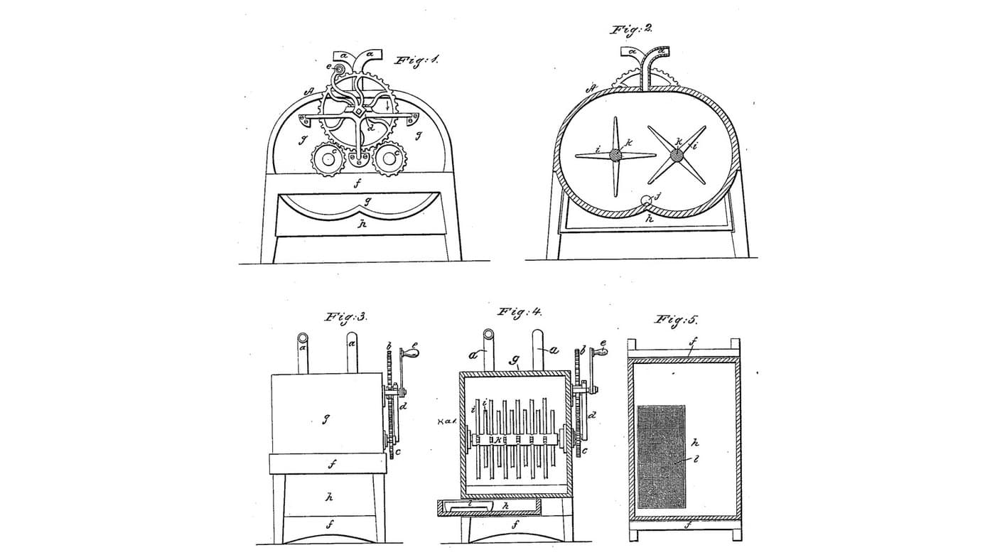
Double Rotary Crag Churn: Two Shafts of Four-Edged Arms Turn Through Each Other in Twin Half-Cylinders
by Buttercup
Woodworking
1
0
0
0
0
0
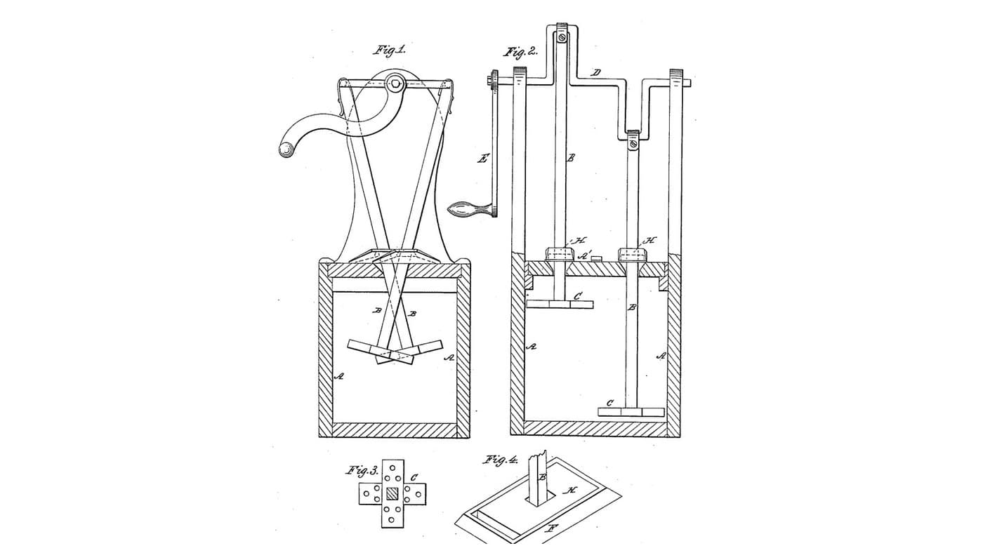
Twin-Crank Slide-Top Churn: Two Dashers on a Bent Crank Shaft, Sliding Plates Keep the Milk In
by Buttercup
Woodworking
2
0
0
0
0
0

Churning Butter from Cream — The 5,000-Year-Old Fat Separation
by TheChef
CRAFT
60
0
0
0
0
0
CC0 Public Domain
This blueprint is released under CC0. You are free to copy, modify, distribute, and use this work for any purpose, without asking permission.
Support the Maker by purchasing products through their Blueprint where they earn a Maker Commission set by Vendors, or create a new iteration of this Blueprint and include it as a connection in your own Blueprint to share revenue.