ART
BEAUTY & WELLNESS
CRAFT
CULTURE & HISTORY
ENTERTAINMENT
ENVIRONMENT
FOOD & DRINKS
REVERSE ENGINEERING
SCIENCES
SPORTS
TECHNOLOGY
WEARABLES
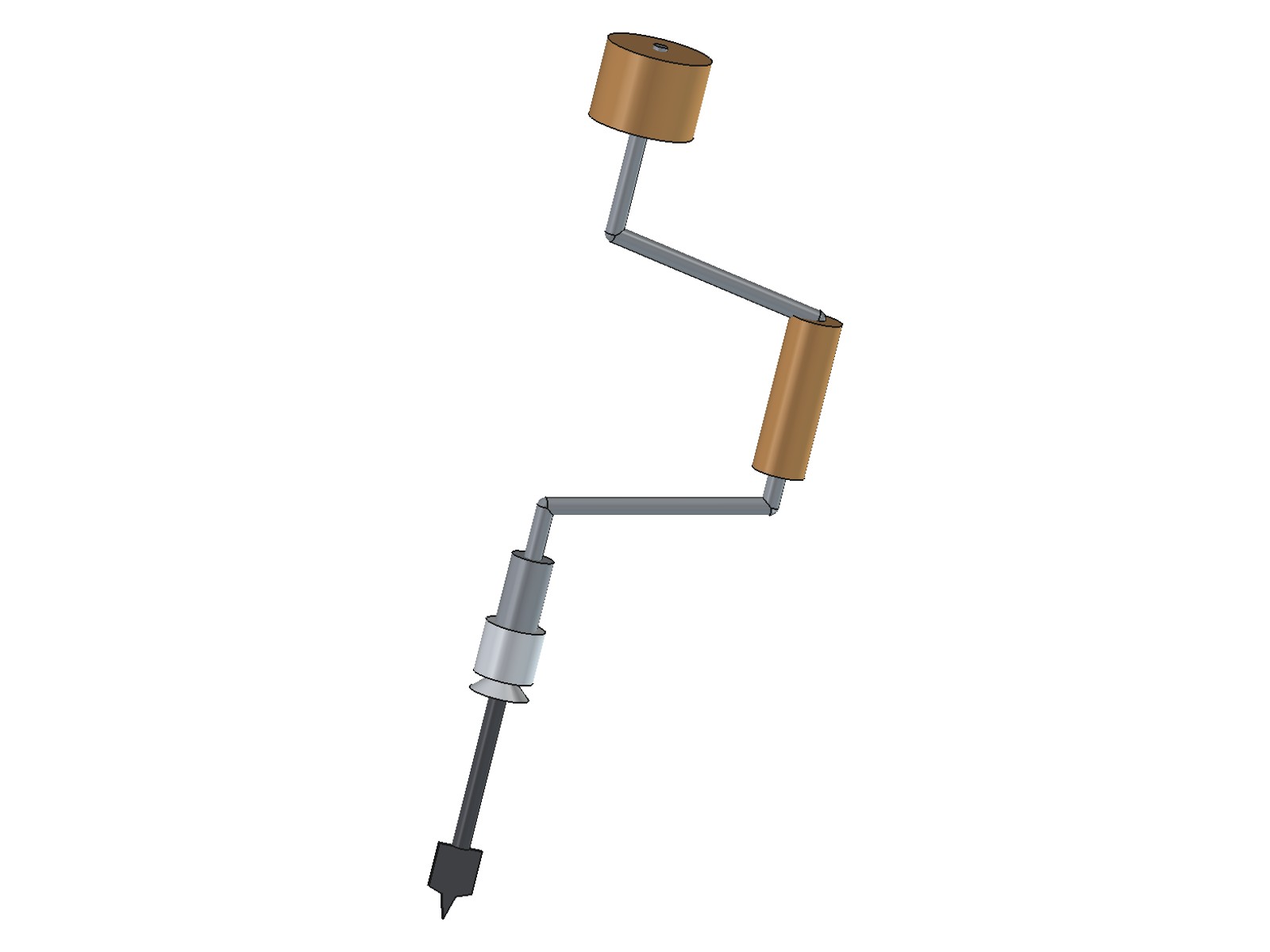


Brace and Bit: a Crank Brace with a Two-Jaw Screw-Thimble Chuck (after Amidon, 1868)
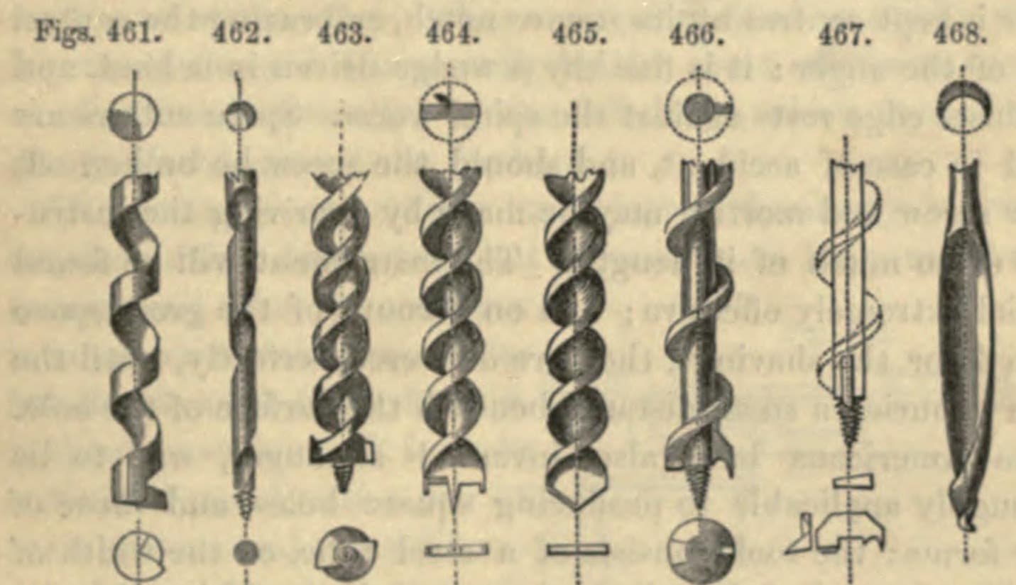
A carpenter's brace: a cranked steel rod with a turning wooden head, a wooden handle sleeve and a chuck that holds the bit. The chuck is Charles Amidon's of 1868: two jaws in a slotted, threaded foot, closed at both ends by a screwed thimble, so they grip a tapered or straight shank firmly. Made on a metal lathe, with a forge for the bends.
Advanced
About 2 days
Instructions
1
1
Watch a brace at work
Watch a brace at work
Boring a square, true hole with a brace and bit (Wood By Wright Extra).
2
2
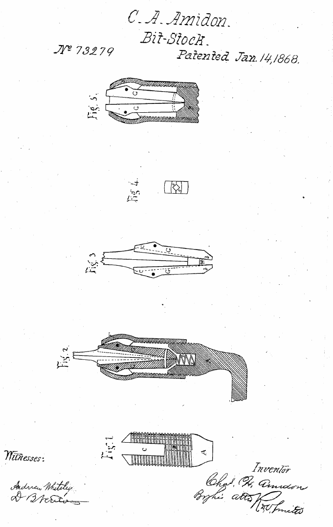
Amidon's chuck, 1868
Amidon's chuck, 1868
US 73,279: the foot of the stock is threaded outside and slotted through; two jaws, loosely pinned at their inner ends, sit in the slot on a spring; grooves in their faces make a tapering square recess for the bit shank. The thimble screws on and its narrowed mouth presses the jaws together at both ends, so they follow the taper of any shank.
3
3
Torque, grip and the rod length
Torque, grip and the rod length
Loading Jupyter Notebook...
4
4
Print the drawings
Print the drawings
Page 1: the chuck parts at 1:1; page 2: the crank layout. Print at 100 % and check the 50 x 10 mm box.
5
5
Turn the foot
Turn the foot
From 24 mm round bar, 60 mm long: cut M24 x 1.5 over the front 30 mm; drill a 10 mm socket 22 mm deep at the back for the crank, and the 8 mm cavity with a 90 degree mouth at the front; saw and file the 8 mm slot, 32 mm deep, right through.
Materials for this step:
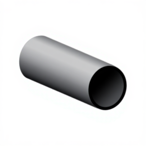 Mild Steel Round Bar1 piece (24 mm x 60 mm)
Tools needed:
 Metal Lathe
 Lathe Tool Set (HSS)
 Drill Bit Set
 Hacksaw
 Metal File
 Digital Caliper 6-Inch
6
6
Make the jaws
Make the jaws
Cut two jaws 46 mm long from 7.5 mm flat bar, 8 mm wide at the pin end widening to 12 mm. File a 90 degree V-groove 3 mm deep along each inner face, bevel both ends 30 degrees, drill the 2 mm pin hole 4 mm from the inner end. Press a 2 mm pin tight into one jaw; it must slide in the other. Check they move freely in the slot.
Materials for this step:
 Mild Steel Flat Bar1 piece (7.5 mm x 12 mm x 100 mm)
 Mild Steel Rod1 piece (2 mm x 12 mm, pin)
Tools needed:
HacksawMetal FileDrill Bit Set Center Punch
 Bench Vise
7
7
Turn the thimble
Turn the thimble
From 34 mm bar, 40 mm long: bore and cut M24 x 1.5 inside, 22 mm deep, then a 60 degree cone narrowing to a 12 mm mouth. Knurl the outside. It must screw fully onto the foot.
Materials for this step:
Mild Steel Round Bar1 piece (34 mm x 45 mm)Tools needed:
Metal LatheLathe Tool Set (HSS) Knurling ToolDigital Caliper 6-Inch
8
8
Bend the crank
Bend the crank
Cut 540 mm of 10 mm rod. Turn 50 mm at one end down to 8 mm (the head journal). Following page 2: make the foot bend, slide the hardwood sleeve (30 mm, bored 10.5 mm, 90 long) onto the rod, make the two handle bends, then the head bend. Heat to a dull red for each bend; keep all bends in one plane and the head and foot legs on one line.
Materials for this step:
Mild Steel Rod1 piece (10 mm x 540 mm) Hardwood Block1 piece (sleeve, 35 x 35 x 95 mm)
Tools needed:
 Blacksmith ForgeBench Vise
 Ball Peen Hammer
 Wood LatheMetal Lathe
9
9
Turn the head and fit it
Turn the head and fit it
Turn a hardwood head 60 mm across and 45 mm thick, bore 8.5 mm through and counterbore the top 16 x 5 mm. Slide a washer on the journal, then the head, then a washer in the counterbore; peen the journal end over so the head turns freely but cannot come off. Oil the wood.
Materials for this step:
Hardwood Block1 piece (head, 65 x 65 x 50 mm) Flat Washer2 piece (8 mm)
 Linseed Oil20 ml
Tools needed:
Wood LatheBall Peen HammerBench Vise10
10
Assemble the chuck
Assemble the chuck
Push the crank's foot end into the foot's socket, drill 4 mm through both and drive in a 4 mm pin, peened both ends. Drop the spring into the cavity, put the jaws in the slot (pinned ends in), and screw the thimble on.
Materials for this step:
Mild Steel Rod1 piece (4 mm x 26 mm, cross pin) Compression Spring Set1 piece (about 6 mm diameter, 15 mm long)
Tools needed:
Drill Bit SetBall Peen HammerBench Vise11
11
Fit a bit and bore
Fit a bit and bore
Back the thimble off, put the bit shank between the jaws and tighten the thimble by hand. Press on the head and turn the handle; keep the brace square to the work.
Materials for this step:
 Spade Bit Set1 piece (one bit, 10 mm octagonal shank)
12
12
Troubleshooting
Troubleshooting
Brace problems and fixes.
Flow
Loading...
13
13
History and honest limits
History and honest limits
Charles H. Amidon, Greenfield, Mass.: US 73,279, "Improvement in Bit-Stocks", 14 January 1868. He compared it with Barber's stock, whose solid socket had to fit the bit head exactly. His patent covers the chuck; the crank and swivel head are the ordinary ones of the time. Ours: every size and the bend order. Not built or tested by us yet.
Materials
8- 1 piece (34 mm x 45 mm)Placeholder
- 1 piece (7.5 mm x 12 mm x 100 mm)Placeholder
- 1 piece (4 mm x 26 mm, cross pin)Placeholder
- 1 piece (head, 65 x 65 x 50 mm)Placeholder
- 2 piece (8 mm)Placeholder
- 20 mlPlaceholder
- 1 piece (about 6 mm diameter, 15 mm long)Placeholder
- 1 piece (one bit, 10 mm octagonal shank)Placeholder
Tools Required
12- Placeholder
- Placeholder
- Placeholder
- Placeholder
- Placeholder
- Placeholder
- Placeholder
- Placeholder
- Placeholder
- Placeholder
- Placeholder
- Placeholder
Design Files
1This blueprint makes
Related Blueprints
These blueprints share knowledge with this one — techniques, materials, or principles that connect them in the learning graph.
CC0 Public Domain
This blueprint is released under CC0. You are free to copy, modify, distribute, and use this work for any purpose, without asking permission.
Support the Maker by purchasing products through their Blueprint where they earn a Maker Commission set by Vendors, or create a new iteration of this Blueprint and include it as a connection in your own Blueprint to share revenue.