Collaboration
ART
BEAUTY & WELLNESS
CRAFT
CULTURE & HISTORY
ENTERTAINMENT
ENVIRONMENT
FOOD & DRINKS
REVERSE ENGINEERING
SCIENCES
SPORTS
TECHNOLOGY
WEARABLES
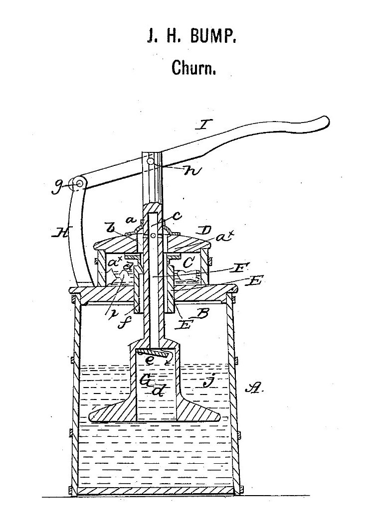

Ice-Chamber Air Churn: The Hollow Dasher Pumps the Same Air Round Through Ice and Cream
James H. Bump of Morris, New York, received US 21,871, dated 26 October 1858, for a churn with an ice chamber on its lid. A hollow dasher with a valve draws air from the ice chamber on every up stroke and forces it into the cream on every down stroke; the air pushed up out of the case returns through a tube into the ice chamber, so the same air goes round, cooled each time.
This rung builds it in a 20-litre bucket with printed parts and a lever.
Intermediate
About 5 hours, plus printing
Instructions
1
1
Air, depth and lever
Air, depth and lever
Loading Jupyter Notebook...
2
2
Air through a hollow dasher, before it
Air through a hollow dasher, before it
Marcell blew room air down a hollow dasher shaft. Bump draws it from an ice chamber and sends it round again.
3
3
Read US 21,871
Read US 21,871
"At every upward movement of the staff F, the air from the chamber C, rushes down within the staff F, into the chamber d ... and as the dasher descends the valve e, closes and the air within will be forced into the cream j, and at the same time the air in the case above the cream will be compressed by the rising of the cream j ... and said air will pass up the space f, into the chamber C".
4
4
Print the tube E
Print the tube E
Tube E, 40 mm across and 155 mm long, with its flange under lid B. PETG, 0.2 mm layers, 30 % infill, 4 walls; wash before first use.
5
5
Print the clamp ring
Print the clamp ring
The ring that clamps tube E's flange, lid B and the chamber floor together. PETG, 0.2 mm layers, 30 % infill, 4 walls; wash before first use.
6
6
Print the box a
Print the box a
Upper box a, 110 mm tall, with the staff's top guide. PETG, 0.2 mm layers, 30 % infill, 4 walls; wash before first use.
7
7
Print the box a'
Print the box a'
Lower box a', with the four notches that do the work of Bump's grooves. PETG, 0.2 mm layers, 30 % infill, 4 walls; wash before first use.
8
8
Print the dasher G
Print the dasher G
The bell dasher, 160 mm across, with chamber d open below. It needs a 160 mm bed; print it top down. PETG, 0.2 mm layers, 30 % infill, 4 walls; wash before first use.
9
9
Print the flap e
Print the flap e
The valve flap with its two hinge knuckles. PETG, 0.2 mm layers, 30 % infill, 4 walls; wash before first use.
10
10
Print the staff head
Print the staff head
The block that closes the staff's top and takes pin h. PETG, 0.2 mm layers, 30 % infill, 4 walls; wash before first use.
11
11
Lid, tube and ice chamber
Lid, tube and ice chamber
Use a food-grade 20-litre bucket and its lid (lid B), and a round food container 200 mm across and 130 mm deep as chamber C, its own lid as lid D. Cut a 40 mm hole in the middle of lid B and of the container's floor. Push tube E up from under lid B, set the container on the lid and the clamp ring over the tube, and fix them with four M4 screws and lock nuts. Cut a 30 mm hole in the middle of lid D.
Materials for this step:
 PETG Filament1 piece
 20-Liter Bucket1 piece
 Food-Grade Storage Container1 piece
 Machine Screws4 pieces
 Nylon Insert Lock Nut4 pieces
Tools needed:
 FDM 3D Printer
 Hole Saw Kit
 Cordless Drill
 Drill Bit Set
 Screwdriver Set
 Adjustable Spanner
12
12
Boxes and hollow staff
Boxes and hollow staff
Bolt box a on top of lid D and box a' under it through their flanges, three M4 screws, the notches of a' against the lid. Cut the stainless tube (16 mm, 1 mm wall) to 549 mm. Drill two 5 mm holes c straight through it, crossed, 389 mm from its foot, and a 4.4 mm hole across it 6 mm and 534 mm from its foot for the cross screws.
Materials for this step:
Machine Screws3 piecesNylon Insert Lock Nut3 pieces Stainless Steel Tube1 piece
Tools needed:
 Tube CutterCordless DrillDrill Bit Set
 Files (Hand File)Screwdriver Set
13
13
Dasher and valve
Dasher and valve
Hang the flap e on the lug in the dasher's chamber with an M3 screw and lock nut so it covers the air hole from below and swings down freely. Push the staff's foot 12 mm into the dasher's top and fix it with an M4 screw across.
Materials for this step:
Machine Screws2 piecesNylon Insert Lock Nut2 piecesTools needed:
Screwdriver SetAdjustable Spanner14
14
Upright and lever
Upright and lever
Cut a hardwood foot 90 x 34 x 30 mm and bolt it to lid B 120 mm from the middle, with two M6 bolts through a hardwood backing strip under the lid. Screw a hardwood upright 30 x 45 mm, 337 mm tall, on it. Cut two lever strips 30 x 12 mm, 480 mm long; drill each 20 mm from one end for pin g and cut a 6.5 mm slot from 110 to 135 mm past it for pin h. Lower the staff through tube E and the boxes, push on the staff head with an M4 screw across, and bolt the strips either side of the upright (pin g) and of the head (pin h) with M6 bolts, washers and lock nuts.
Materials for this step:
 Hardwood Board1 piece
 Hex Bolt Assortment4 pieces
 Flat Washer8 piecesNylon Insert Lock Nut5 pieces
 #8 x 1" Wood Screw4 piecesMachine Screws1 piece
Tools needed:
 Hand SawCordless DrillDrill Bit SetFiles (Hand File)
 SandpaperAdjustable Spanner
 Tape Measure
15
15
The build in 3D
The build in 3D
FreeCAD model of this build at mid stroke, the near quarter of the bucket, chamber and boxes cut away: lid B with tube E, chamber C and lid D, boxes a and a', the hollow staff with its holes c, the bell dasher with flap e, the upright and the forked lever.
16
16
Churn
Churn
Pour 8 litres of heavy cream at about 15 °C into the bucket, checked with the thermometer. Fit lid B with the dasher in place, fill chamber C with crushed ice round tube E and close lid D. Work the lever up and down steadily, the full 100 mm stroke, and time it. When the butter comes, lift the lid out, pour off the buttermilk, wash the butter in cold water until it runs clear, work in a pinch of salt and weigh it.
Materials for this step:
 Heavy Cream8 l
 Crushed Ice2 kg
 Coarse Sea Salt1 piece
 Water1 piece
Tools needed:
 Leave-In Probe Thermometer
 Stopwatch
 Digital Kitchen Scale
 Stainless Steel Mixing Bowl (Large)
17
17
Troubleshooting
Troubleshooting
Ice-chamber churn troubleshooting.
Flow
Loading...
18
18
History and honest limits
History and honest limits
**James H. Bump** of Morris, Otsego County, New York, US 21,871, 26 October 1858, "Churn". He held that the cream, "by the absorption of oxygen is fully acetified" and kept cool by the iced air, gives butter "of a superior quality". He disclaimed a hollow dasher rod for air and forcing air into cream as done before, and claimed only the chamber C through which the air is made to circulate. He gave no sizes and named only "metal boxes": every size, material and the 8 litres at 15 °C are ours. Our notches in box a' stand in for his grooves cut in lid D.
Materials
14- 1 piecePlaceholder
- 1 piecePlaceholder
- 1 piecePlaceholder
- 10 piecesPlaceholder
- 14 piecesPlaceholder
- 1 piecePlaceholder
- 1 piecePlaceholder
- 4 piecesPlaceholder
- 8 piecesPlaceholder
- 4 piecesPlaceholder
- 8 lPlaceholder
- 2 kgPlaceholder
- 1 piecePlaceholder
- 1 piecePlaceholder
Tools Required
15- Placeholder
- Placeholder
- 1 vendor sell this, none ship to you yetPlaceholder
- Placeholder
- Placeholder
- Placeholder
- Placeholder
- Placeholder
- Placeholder
- Placeholder
- 1 vendor sell this, none ship to you yetPlaceholder
- Placeholder
- Placeholder
- Placeholder
- Placeholder
Design Files
8This blueprint makes


Related Blueprints
These blueprints share knowledge with this one — techniques, materials, or principles that connect them in the learning graph.
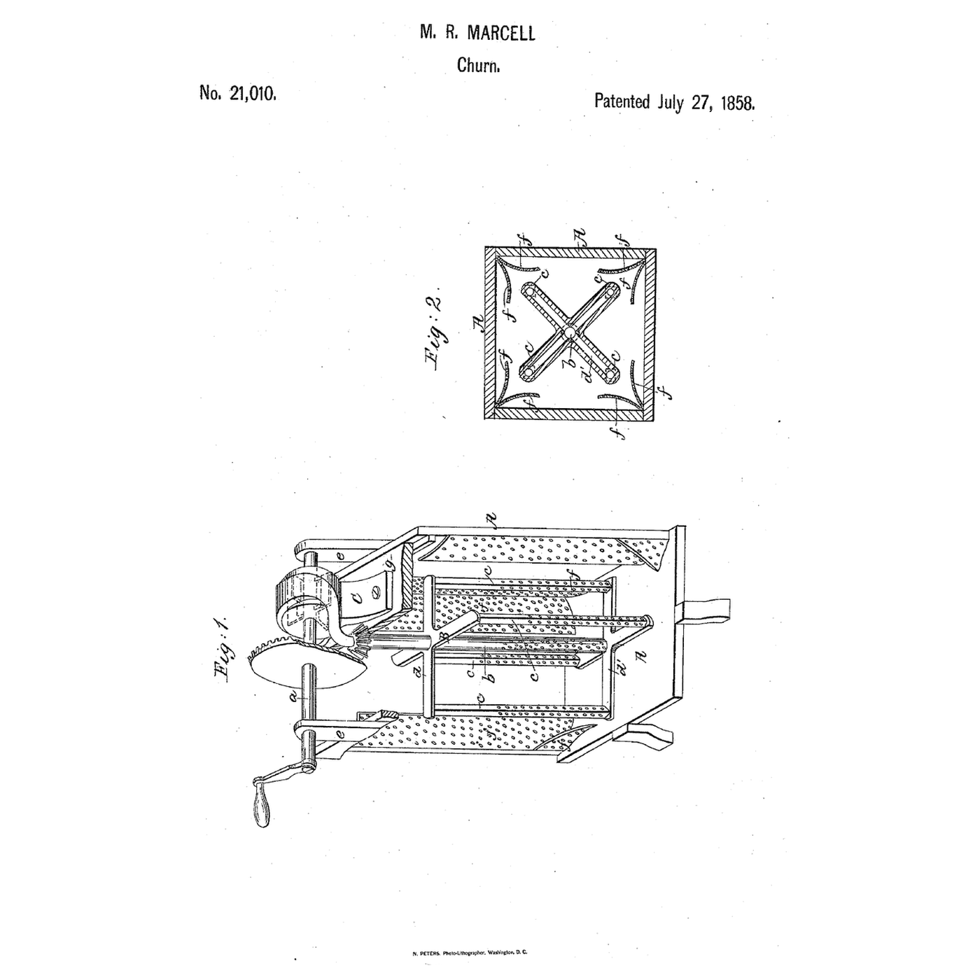
Fan-Blown Jet Dasher Churn: A Fan on the Crank Shaft Blows Air Out Through the Dasher Below the Cream
by Buttercup
FOOD & DRINKS
42
0
0
0
0
0
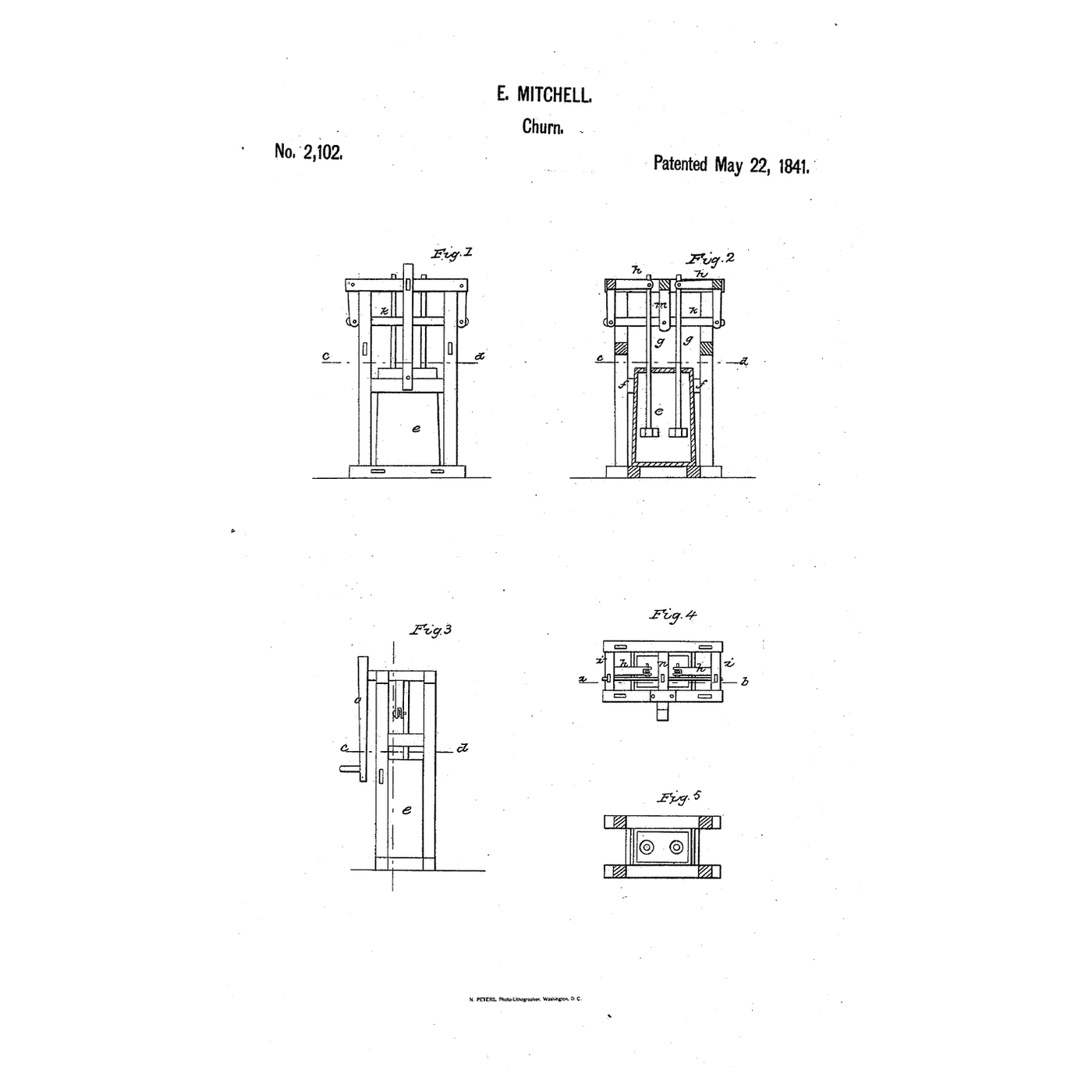
Double-Dasher Lever Churn: Swing One Lever, One Dasher Rises as the Other Falls
by Woody
Woodworking
40
0
0
0
0
0

Churning Butter from Cream — The 5,000-Year-Old Fat Separation
by TheChef
CRAFT
60
0
0
0
0
0
CC0 Public Domain
This blueprint is released under CC0. You are free to copy, modify, distribute, and use this work for any purpose, without asking permission.
Support the Maker by purchasing products through their Blueprint where they earn a Maker Commission set by Vendors, or create a new iteration of this Blueprint and include it as a connection in your own Blueprint to share revenue.