Collaboration
ART
BEAUTY & WELLNESS
CRAFT
CULTURE & HISTORY
ENTERTAINMENT
ENVIRONMENT
FOOD & DRINKS
REVERSE ENGINEERING
SCIENCES
SPORTS
TECHNOLOGY
WEARABLES
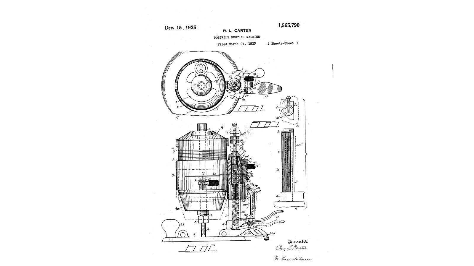


Rack-and-Pawl Plunge Router: The Motor Rides One Post on a Spring and Steps Down a Tooth at a Time (Carter, 1925)
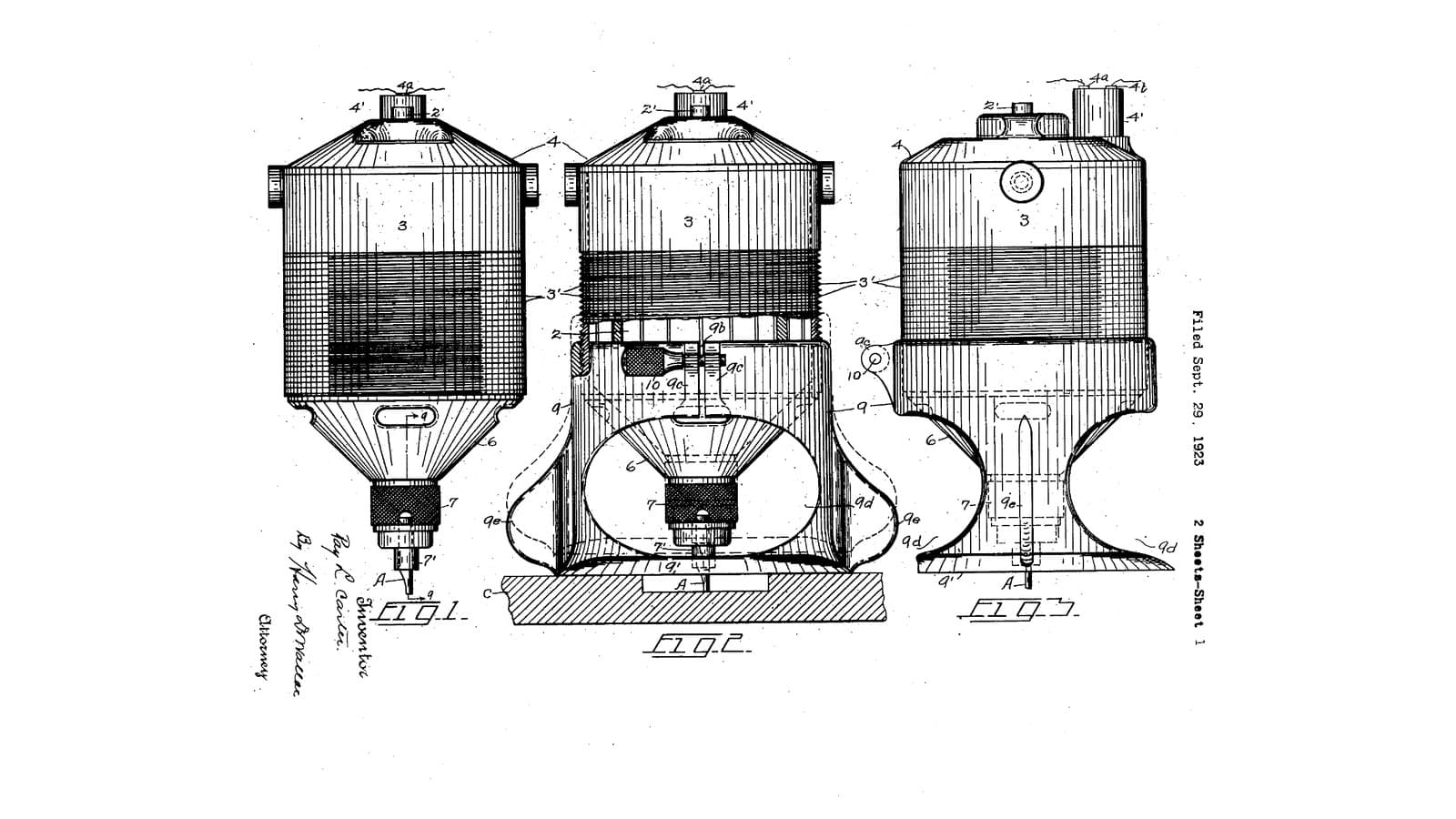
Ray L. Carter of Syracuse, New York, improved his 1924 router with US 1,565,790, dated 15 December 1925. The motor's holder now slides up and down a single strong post on a large round base, and a spring inside the post holds it up off the work. Each press of a lever moves the holder down one tooth of a rack, so a deep cavity is cut in stages. A locking pawl holds each step. Gauge nuts on a plunger stem set the final depth, and pressing the pawl's foot lets the spring lift the cutter clear.
We reuse our 1924 router's printed motor casing in a printed holder on a square steel post. The sizes are ours.
Advanced
About 3 days
Instructions
1
1
Cutting deep in stages
Cutting deep in stages
Loading Jupyter Notebook...
2
2
Read US 1,565,790
Read US 1,565,790
"By this arrangement cavities of considerable depth may be routed by successive stages wherein each stage represents the normal depth the tool is designed to cut."
3
3
The motor and its casing come from the 1924 router
The motor and its casing come from the 1924 router
Print the casing and fit the motor, collet and switch exactly as in Carter's 1924 router; here the casing screws into a holder on a post instead of into a base.
4
4
Print the holder
Print the holder
The holder 7: a split ring threaded for the 1924 casing, clamp lugs for a thumb screw, and beside it the guide 7c with a square opening for a 1 in tube, a recess for the gib plate, two set-screw holes and the rack 17 of 3 mm teeth on its outer face. Print it rack upright. PETG, 0.2 mm layers, 40 % infill, 5 walls; no supports.
5
5
Print the base
Print the base
The base 9: a round plate 170 mm across with a 50 mm opening, and the boss 9' with a square socket for the post and a hole for its cross bolt. Print it plate down. PETG, 0.2 mm layers, 40 % infill, 5 walls; no supports.
6
6
The hollow post 8
The hollow post 8
Cut 1 inch square steel tube 200 mm long. Saw and file a slot 8b 6 mm wide and 100 mm long down the middle of one wall, starting 40 mm from the top. Push the post into the base's socket and bolt it through with an M6 bolt and lock nut. Drop a compression spring 10 into the post, then a plunger 13: a block of flat bar that slides in the tube, tapped M6 on its back for the screw that runs in the slot, with an M6 rod 13' standing up from it. Screw a flat-bar cap 12 across the post's top with a hole for the rod, and run two gauge nuts 14, 14' onto the rod above it.
Materials for this step:
 Mild Steel Square Tube 1" x 1"1 piece
 Mild Steel Flat Bar1 piece
 Compression Spring Set1 piece
 Threaded Rod1 piece
 Hex Nut2 pieces
 Hex Bolt Assortment3 pieces
 Nylon Insert Lock Nut1 piece
Tools needed:
 Hacksaw
 File Set
 Bench Vise
 Drill Press
 Drill Bit Set
 Tap and Die Set
 Tap Wrench
 Adjustable Spanner
 Safety Glasses
7
7
Holder on the post
Holder on the post
Print the holder and base. Lay a strip of flat bar in the guide's recess 15 as the gib plate 15' and run two M5 set screws 16 against it, one with a wing nut on its head to lock the holder by hand. Slide the guide down over the post and fix it to the plunger with an M6 screw through the slot. Set the screws so the holder slides freely without rattling. Screw the 1924 motor casing into the holder and lock it with an M5 screw and wing nut through the lugs.
Materials for this step:
 PETG Filament1 pieceMild Steel Flat Bar1 piece
 Cup Point Set Screw2 pieces
 Wing Nut2 pieces
 Socket Head Cap Screw2 pieces
Tools needed:
 FDM 3D Printer
 Deburring Tool
 Hex Key Set
 Digital Caliper 6-Inch
8
8
Pawls and lever
Pawls and lever
File a pawl 18 from flat bar with a hook 18' at its top to catch the rack's teeth, and a locking pawl 20 with a tooth 20' at its top and its lower end bent out as a foot 20d. Pivot the locking pawl on the base's boss with an M5 screw, held against the rack by a spring-steel leaf 20b. Pivot one end of a lever 19 on the boss and the pawl's lower end to the lever partway along, with a second leaf 20c holding the pawl to the rack. Each press of the lever's handle pulls the holder down one tooth, and the locking pawl drops in under it.
Materials for this step:
Mild Steel Flat Bar2 pieces Spring Steel Strip1 pieceSocket Head Cap Screw3 piecesNylon Insert Lock Nut3 pieces
Tools needed:
HacksawFile SetBench ViseDrill PressDrill Bit SetAdjustable Spanner9
9
Rout a deep recess
Rout a deep recess
Fit a straight bit. Set the gauge nuts so the plunger's rod stops on the cap at the depth wanted. Clamp a board, rest the base on it with the cutter clear, switch on, press the lever once and move the router across the area; press again and repeat, until the nuts stop it. Press the locking pawl's foot and the spring lifts the cutter out.
Tools needed:
 Router Bit Set
 Hardwood Board
 Bar ClampSafety Glasses
10
10
Troubleshooting
Troubleshooting
Plunge router troubleshooting.
Flow
Loading...
11
11
History and honest limits
History and honest limits
**Ray L. Carter** of Syracuse, New York, US 1,565,790, dated 15 December 1925, filed 21 March 1925, improving his US 1,514,894. He describes a holder "formed at one side with a guide portion having an angular vertical opening, for slidably mounting the holder upon a pedestal or post of substantially the same angularity", a coil spring housed in the pedestal, a ratchet rack and pawl to move the motor step by step, a locking pawl, gauge nuts, and a plate with set screws to take up wear. His post is triangular and cast; ours is 1 inch square steel tube. His holder and base are metal; ours are printed PETG. His motor ran on mains; ours is the small DC motor of our 1924 router. The sizes are ours.
Materials
12- Placeholder
- 2 piecesPlaceholder
- 1 piecePlaceholder
- 1 piecePlaceholder
- 2 piecesPlaceholder
- 3 piecesPlaceholder
- 4 piecesPlaceholder
- 1 piecePlaceholder
- 2 piecesPlaceholder
- 2 piecesPlaceholder
- 5 piecesPlaceholder
- 1 piecePlaceholder
Tools Required
16- Placeholder
- Placeholder
- Placeholder
- Placeholder
- Placeholder
- Placeholder
- Placeholder
- Placeholder
- Placeholder
- Placeholder
- Placeholder
- Placeholder
- Placeholder
- 1 vendor sell this, none ship to you yetPlaceholder
- Placeholder
- Placeholder
Design Files
2This blueprint makes

Related Blueprints
These blueprints share knowledge with this one — techniques, materials, or principles that connect them in the learning graph.
CC0 Public Domain
This blueprint is released under CC0. You are free to copy, modify, distribute, and use this work for any purpose, without asking permission.
Support the Maker by purchasing products through their Blueprint where they earn a Maker Commission set by Vendors, or create a new iteration of this Blueprint and include it as a connection in your own Blueprint to share revenue.