Collaboration
ART
BEAUTY & WELLNESS
CRAFT
CULTURE & HISTORY
ENTERTAINMENT
ENVIRONMENT
FOOD & DRINKS
REVERSE ENGINEERING
SCIENCES
SPORTS
TECHNOLOGY
WEARABLES
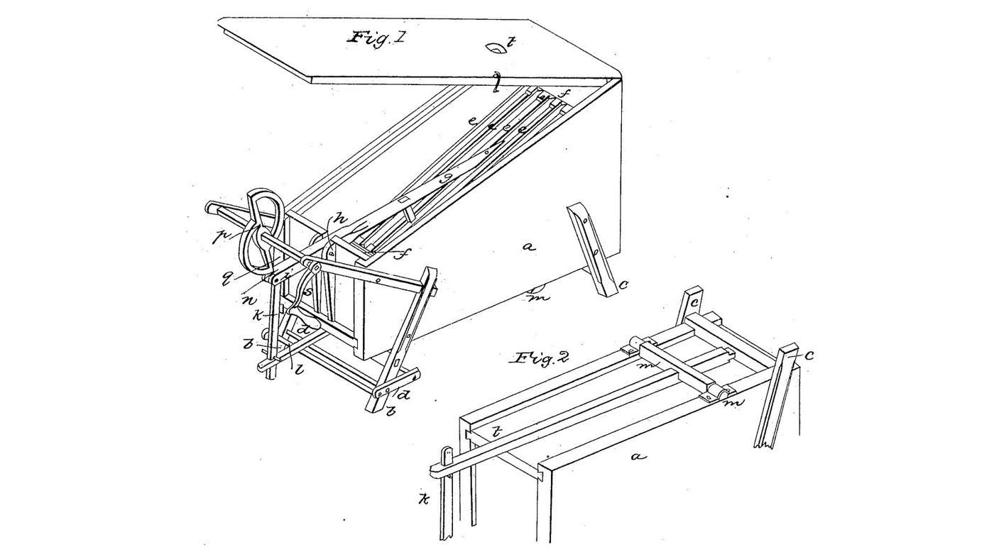

Spring-Pole Cam Churn: A Two-Arc Cam Lifts a Hinged Strip Dasher and a Wooden Spring Pole Drives It Down
Alexander W. Cunningham of West Middleton, Pennsylvania, received US 27,276, dated 28 February 1860, for a churn. A box deeper at the rear holds a dasher of strips set edge-on, hinged on a lever at the front. A cam of two semicircular arcs lifts the dasher slowly; when each arc's end passes the roller, a spring pole of hickory under the box drives it down with force. Two strokes to each turn of the crank.
The patent gives no sizes; every size here is ours.
Advanced
About 3 days, plus printing
Instructions
1
1
Two half-circles on one shaft
Two half-circles on one shaft
Loading Jupyter Notebook...
2
2
Two dasher strokes to a turn, one week before
Two dasher strokes to a turn, one week before
Clement gets two strokes a turn from a toggle. Cunningham gets them from a cam of two arcs.
3
3
A dasher worked by a lever
A dasher worked by a lever
Cooper's dasher hangs on levers. Cunningham hinges his whole dasher on one lever at the box's front.
4
4
Read US 27,276
Read US 27,276
"The cam p consists of two semicircular arcs, one extremity of each arc being placed at the center of the other semicircular arc, the arcs being united by their chords and the shaft passing through the chords at a point midway between the inner extremities of the two arcs." ... "On turning the shaft, the dasher is raised up gradually, and falls suddenly with the full force of the spring pole."
5
5
Print the cam p
Print the cam p
Two semicircular arcs of 80 mm radius, a band 10 mm thick and 20 wide, joined along their chords by a bar 250 mm long, with a hub bored 20.6 mm midway between the arcs' inner ends. PETG, 0.2 mm layers, 100 % infill.
6
6
Box a, cover and feet
Box a, cover and feet
From 20 mm hardwood board make a box 700 mm long and 260 wide inside, 200 mm deep at the front end and 375 at the rear: cut the sides with their lower edges sloping 175 mm over the length, glue and screw the ends and bottom between them, and seal the inside joints with silicone sealant. Cut a slot 44 x 95 mm in the front end's middle, 20 to 115 mm above the inside floor, for the lever. Hinge a cover on the top and drill a 10 mm air hole t in it. Screw two front feet b, 40 x 40 mm, 460 mm long, to the sides' outer faces 160 mm behind the front, and two rear feet c, 340 mm long, 640 mm behind it, so the sides stand upright and the bottom falls to the rear. Hinge a small frame d (two legs 305 mm and a bar) to the front feet, folded up; let it down to raise the front end.
Materials for this step:
 Hardwood Board4 pieces
 Wood Glue1 piece
 Wood Screws60 pieces
 Silicone Sealant1 piece
 Cabinet Butt Hinge4 pieces
Tools needed:
 Table Saw
 Jigsaw
 Cordless Drill
 Drill Bit Set
 Bar Clamp
 Screwdriver Set
 Tape Measure
 Sandpaper
7
7
Dasher strips e, cross pieces f and lever g
Dasher strips e, cross pieces f and lever g
Cut five hardwood strips 20 x 20 mm, 600 mm long, and set them in two cross pieces f, 30 x 25 mm, 240 long, 54 mm apart and turned 45 degrees, so each presents an edge to the cream. Cut a hardwood lever 40 x 30 mm, 977 mm long; bore it 12.8 mm across 265 mm from one end for the pivot h, and 15 mm from that end for the pin i; saw a slot 22 mm wide from that end for 165 mm, for the roller. Screw the cross pieces under the long arm so the strips lie 2 mm above the floor when it rests along it. Pivot the lever on a 12 mm stainless pin in two hardwood brackets on the front end's outer face, 35 mm out and 70 mm above the inside floor, the long arm through the slot.
Materials for this step:
Hardwood Board2 piecesWood Glue1 pieceWood Screws12 pieces Stainless Steel Rod1 piece
 Split Pin2 pieces
Tools needed:
Table SawJigsawCordless DrillDrill Bit Set Hacksaw
 Files (Hand File)Bar ClampScrewdriver Set
8
8
Roller n, pitman k, spring pole l and cross piece m
Roller n, pitman k, spring pole l and cross piece m
Cut a roller 40 mm across and 20 long from hardwood dowel, bore it 12.6 mm and set it in the lever's slot on a 12 mm stainless pin i. On the pin's ends outside the lever hang two hardwood pitman links 8 x 30 mm with holes 200 mm apart. Cut a spring pole 40 x 25 mm, about 1010 mm long, from straight-grained ash (the patent: "hickory or other suitable wood"); screw its rear end to a block under the bottom's rear, run it forward under the box, and hold it up on a hardwood cross piece m hung from the sides 590 mm from the front. Pin its front end between the pitman links; it should lift the lever's short arm so the dasher rests on the floor.
Materials for this step:
 Hardwood Dowels1 pieceStainless Steel Rod1 pieceHardwood Board1 piece
 Ash Board1 pieceWood Screws8 piecesSplit Pin4 pieces
Tools needed:
Table SawCordless DrillDrill Bit SetHacksawFiles (Hand File) Bench ViseScrewdriver Set
9
9
Arms, shaft q, cam p and crank s
Arms, shaft q, cam p and crank s
Bolt two hardwood arms 15 x 30 mm, 450 mm long, along the box's sides, reaching 300 mm out in front, and bore their ends 20.8 mm across directly above the roller, 70 mm above its centre at rest. Pass a 20 mm stainless shaft through them with the cam on it over the roller, held by collars; fit a hardwood crank 150 mm long with a dowel handle on one end. Set the cam so each arc meets the roller by its inner end as the crank turns.
Materials for this step:
Hardwood Board1 piece Carriage Bolt4 pieces
 Wing Nut4 piecesStainless Steel Rod1 piece
 Shaft Collar2 piecesHardwood Dowels1 pieceWood Glue1 piece
 PETG Filament1 piece
Tools needed:
 FDM 3D PrinterTable SawCordless DrillDrill Bit Set
 Spade Bit SetHacksawFiles (Hand File)
 Adjustable Spanner
10
10
The build in 3D
The build in 3D
FreeCAD model of this build, the box cut through the middle: the strip dasher on the lever g, the pivot h, the roller and pitman, the spring pole under the bottom on the cross piece m, and the two-arc cam on its shaft and crank in front.
11
11
Churn
Churn
Pour in about 15 litres of heavy cream at about 15 °C, checked with the thermometer: no more, as the patent says the box "must not be filled so full as to cover the dasher with cream when it is raised". Close the cover and turn the crank steadily, timing it: the dasher rises slowly and falls hard, twice a turn. When the butter comes, let down the frame d to raise the front end, as the patent advises, so everything runs to the rear; lift the cover and dasher, take out the butter, pour the buttermilk into a bowl, wash the butter in cold water until it runs clear, salt and weigh it.
Materials for this step:
 Heavy Cream15 l
 Coarse Sea Salt1 piece
 Water1 piece
Tools needed:
 Leave-In Probe Thermometer
 Stopwatch
 Digital Kitchen Scale
 Stainless Steel Mixing Bowl (Large)
12
12
Troubleshooting
Troubleshooting
Spring-pole cam churn troubleshooting.
Flow
Loading...
13
13
History and honest limits
History and honest limits
**Alexander W. Cunningham** of West Middleton, Washington County, Pennsylvania, US 27,276, 28 February 1860, "Churn". He claimed the spring dasher worked by a cam, made of longitudinal strips presenting their angular edge to the cream, with a box deeper at one end than the other. The text calls the frame on the front feet both d and u. The patent gives no sizes or materials beyond the hickory pole; every size here is ours, our pole is ash, and our cam is printed.
Materials
16- 4 piecesPlaceholder
- 3 piecesPlaceholder
- 80 piecesPlaceholder
- 1 piecePlaceholder
- 4 piecesPlaceholder
- 1 piecePlaceholder
- 6 piecesPlaceholder
- 1 piecePlaceholder
- 1 piecePlaceholder
- 4 piecesPlaceholder
- 4 piecesPlaceholder
- 2 piecesPlaceholder
- 1 piecePlaceholder
- 15 lPlaceholder
- 1 piecePlaceholder
- 1 piecePlaceholder
Tools Required
18- 1 vendor sell this, none ship to you yetPlaceholder
- 1 vendor sell this, none ship to you yetPlaceholder
- 1 vendor sell this, none ship to you yetPlaceholder
- Placeholder
- Placeholder
- Placeholder
- 1 vendor sell this, none ship to you yetPlaceholder
- Placeholder
- Placeholder
- Placeholder
- Placeholder
- Placeholder
- Placeholder
- Placeholder
- Placeholder
- Placeholder
- Placeholder
- Placeholder
Design Files
2This blueprint makes


Related Blueprints
These blueprints share knowledge with this one — techniques, materials, or principles that connect them in the learning graph.
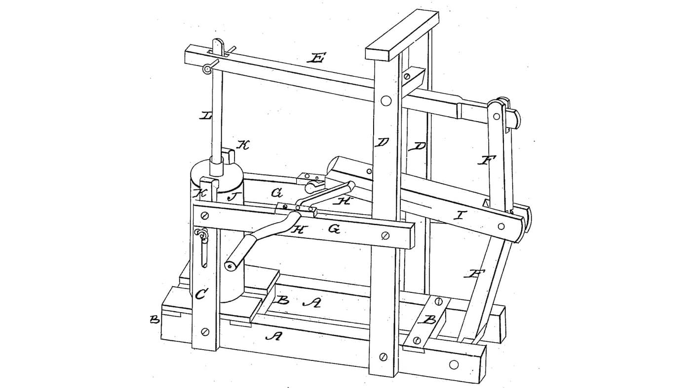
Toggle-Lever Churn: A Crank Crooks and Straightens a Jointed Lever, Rocking a Walking Beam Twice Each Turn
by Buttercup
Woodworking
0
0
0
0
0
0
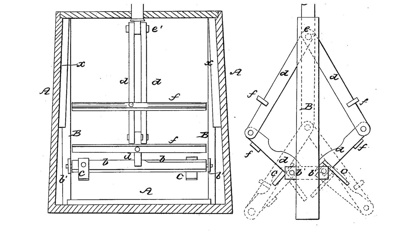
Folding-Lever Dasher Churn: The Dash Rod Folds Two Levers and Swings the Agitators Side to Side
by Buttercup
Woodworking
1
0
0
0
0
0

Churning Butter from Cream — The 5,000-Year-Old Fat Separation
by TheChef
CRAFT
60
0
0
0
0
0
CC0 Public Domain
This blueprint is released under CC0. You are free to copy, modify, distribute, and use this work for any purpose, without asking permission.
Support the Maker by purchasing products through their Blueprint where they earn a Maker Commission set by Vendors, or create a new iteration of this Blueprint and include it as a connection in your own Blueprint to share revenue.