Collaboration
ART
BEAUTY & WELLNESS
CRAFT
CULTURE & HISTORY
ENTERTAINMENT
ENVIRONMENT
FOOD & DRINKS
REVERSE ENGINEERING
SCIENCES
SPORTS
TECHNOLOGY
WEARABLES
Toggle-Lever Churn: A Crank Crooks and Straightens a Jointed Lever, Rocking a Walking Beam Twice Each Turn
Buttercup

Created by

Buttercup

11. November 2026IE
0
0
0
0
0

Toggle-Lever Churn: A Crank Crooks and Straightens a Jointed Lever, Rocking a Walking Beam Twice Each Turn

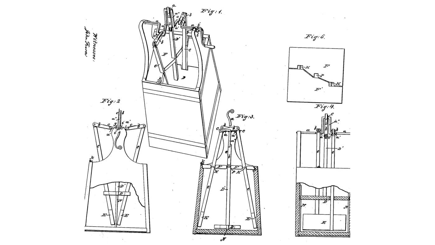
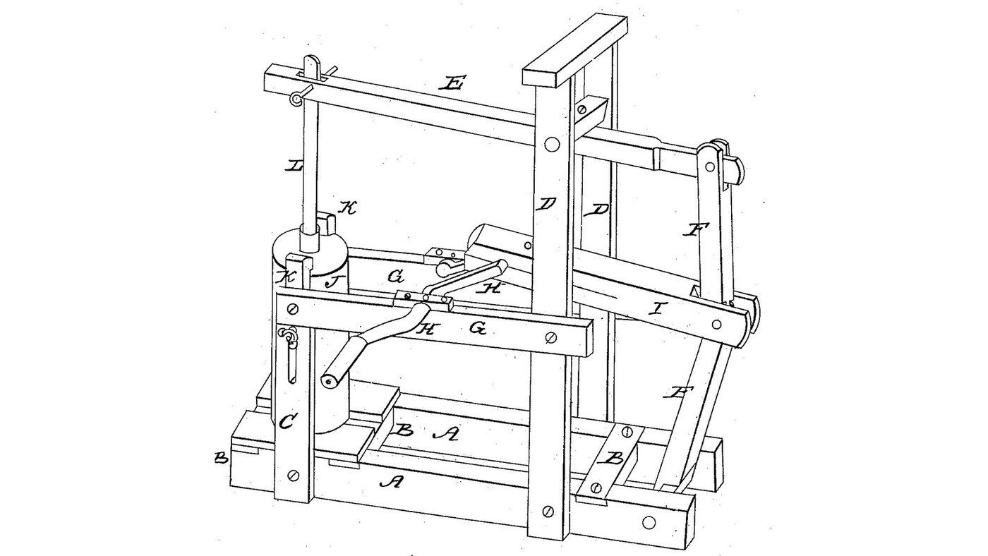
Edwin B. Clement of Barnet, Vermont, received US 27,205, dated 21 February 1860, for a churn. A walking beam on tall posts carries the dasher staff at one end; its other end is joined to a toggle-jointed lever standing on a shaft in the ends of the sills. A crank pushes and pulls the toggle's knee, crooking and straightening it, so the dasher goes "up and down twice to one revolution of the crank". The patent gives no sizes; every size here is ours.
Advanced
About 3 days, plus printing

Instructions

1

Two strokes to one turn

Loading Jupyter Notebook...
2

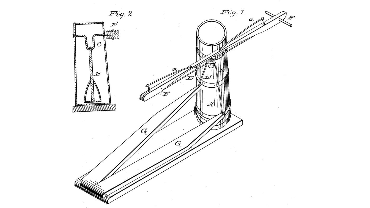
A crank that strokes a dasher, the year before

Austin's crank strokes the dasher once a turn. Clement's toggle gives two strokes a turn.
3

A crank-driven dasher, one week before

Willson turns his dasher's crank with a bow. Clement keeps the hand crank and adds a beam and toggle.
4

Read US 27,205

"One end of the walking beam is connected with a toggle jointed lever, the lower end of which lever is connected with a shaft that turns or rocks in the ends of the sills A, A, see letter F F." ... "I now come to the operation, which is simply to turn the crank H, which will alternately crook and straighten the toggle jointed lever causing the dasher to move up and down twice to one revolution of the crank."
5

Print the dasher

Cone dasher 160 mm across, open underneath, with a socket 22.6 mm across for the dasher staff. PETG, 0.2 mm layers, 40 % infill, 4 walls.
Design FileSTLCC0 - Free
6

Frame: sills A, cross ties B, posts C and D

From pine lumber cut two sills 80 x 100 mm, 1250 mm long, and lay them 400 mm apart, centre to centre. Let three cross ties 80 x 30 mm into their tops: one under the churn's place near one end, one in the middle, one 100 mm in from the far end. Screw a board 340 x 300 mm on the end tie, between the sills, for the churn to stand on. Let two posts C, 60 x 60 mm, into the sills either side of the churn's place, reaching 560 mm above the floor, and two posts D 650 mm along from them, reaching 760 mm. Bore the posts D 17 mm across, 650 mm above the floor, for the beam's pivot, and the sills' far ends 21 mm across, 60 mm above the floor and 50 mm from the ends, for the rocking shaft.

Materials for this step:

Pine LumberPine Lumber4 pieces
Hardwood BoardHardwood Board1 piece
Wood ScrewsWood Screws40 pieces
Wood GlueWood Glue1 piece

Tools needed:

Table SawTable Saw
Cordless DrillCordless Drill
Drill Bit SetDrill Bit Set
Spade Bit SetSpade Bit Set
Bar ClampBar Clamp
Screwdriver SetScrewdriver Set
Tape MeasureTape Measure
7

Walking beam E and dasher staff L

Cut a hardwood beam 40 x 60 mm, 1010 mm long. Cut a slot 28 x 80 mm through it 30 mm from one end for the staff, and bore 12.8 mm across that slot. Bore 16.8 mm across 650 mm from the slot's centre for a 16 mm stainless pivot through the posts D, and 12.8 mm across 300 mm beyond the pivot for the toggle's pin. Glue a 22 mm hardwood staff into the dasher's socket so its top is 459 mm above the dasher's underside, and bore it 12.8 mm across 414 mm up from the underside; pin it in the beam's slot with a 12 mm stainless pin and split pins.

Materials for this step:

Hardwood BoardHardwood Board1 piece
Hardwood DowelsHardwood Dowels1 piece
Wood GlueWood Glue1 piece
Stainless Steel RodStainless Steel Rod1 piece
Shaft CollarShaft Collar2 pieces
Split PinSplit Pin2 pieces
PETG FilamentPETG Filament1 piece

Tools needed:

FDM 3D PrinterFDM 3D Printer
Table SawTable Saw
JigsawJigsaw
Cordless DrillCordless Drill
Drill Bit SetDrill Bit Set
HacksawHacksaw
Files (Hand File)Files (Hand File)
SandpaperSandpaper
8

Toggle-jointed lever F and rocking shaft

Pass a 20 mm stainless rod through the sills' far ends as the rocking shaft. Cut four hardwood links 15 x 40 mm, each with two 12.8 mm holes 320 mm apart: a pair of lower links on the rocking shaft, and a pair of upper links on the beam's end pin, either side of the beam. Join the four at the knee with one 12 mm stainless pin, the upper pair inside the lower pair, leaving the middle free for the connecting shaft. Secure every pin with split pins.

Materials for this step:

Stainless Steel RodStainless Steel Rod1 piece
Hardwood BoardHardwood Board1 piece
Shaft CollarShaft Collar2 pieces
Split PinSplit Pin6 pieces

Tools needed:

Table SawTable Saw
Cordless DrillCordless Drill
Drill Bit SetDrill Bit Set
HacksawHacksaw
Files (Hand File)Files (Hand File)
Bench ViseBench Vise
SandpaperSandpaper
9

Bars G, crank H and connecting shaft I

Screw a hardwood bar G 25 x 60 mm along the outside of each side, from post C to post D, 400 mm above the floor, and bore both 20.8 mm across 378 mm from the posts C. Cut a 20 mm stainless crank shaft 610 mm long, through both bars and 85 mm beyond one. Build the crank in the middle: two hardwood webs 30 x 14 mm, glued and pinned to the shaft with a 32 mm gap, carrying a 12 mm stainless crank pin 150 mm out; cut the shaft away between them. Outside the bar fit a hardwood arm 130 mm long with a dowel handle. Cut a hardwood connecting shaft I 30 x 40 mm with 12.8 mm holes 600 mm apart, from the crank pin to the knee pin. Fit collars either side of the bars.

Materials for this step:

Hardwood BoardHardwood Board2 pieces
Stainless Steel RodStainless Steel Rod1 piece
Hardwood DowelsHardwood Dowels1 piece
Wood GlueWood Glue1 piece
Wood ScrewsWood Screws8 pieces
Shaft CollarShaft Collar2 pieces
Split PinSplit Pin2 pieces

Tools needed:

Table SawTable Saw
Cordless DrillCordless Drill
Drill Bit SetDrill Bit Set
Spade Bit SetSpade Bit Set
HacksawHacksaw
Files (Hand File)Files (Hand File)
Bench ViseBench Vise
Bar ClampBar Clamp
Screwdriver SetScrewdriver Set
10

Churn J and hooks K

Bore a 48 mm hole in the centre of the bucket's lid for the staff. Bend two hooks from mild steel flat bar to reach from the posts C over the bucket's rim, and fasten each to its post with a carriage bolt and wing nut, as the patent's hooks are "provided each with a bolt and nut and fastened to the posts C".

Materials for this step:

20-Liter Bucket20-Liter Bucket1 piece
Mild Steel Flat BarMild Steel Flat Bar1 piece
Carriage BoltCarriage Bolt2 pieces
Wing NutWing Nut2 pieces

Tools needed:

Cordless DrillCordless Drill
Drill Bit SetDrill Bit Set
Spade Bit SetSpade Bit Set
HacksawHacksaw
Bench ViseBench Vise
Files (Hand File)Files (Hand File)
Adjustable SpannerAdjustable Spanner
11

The build in 3D

FreeCAD model of this build, the churn cut through the middle: the sills, ties and posts, the walking beam on the posts D, the dasher staff, the toggle-jointed lever on the rocking shaft, the crank in the bars G and the connecting shaft to the toggle's knee.
Design FileBLENDCC0 - Free
12

Churn

Lift the beam's dasher end, stand the bucket on its board with about 10 litres of heavy cream at about 15 °C, checked with the thermometer, lower the dasher in, put on the lid over the staff and fasten the hooks. Turn the crank steadily, timing it. When the butter comes, unhook the bucket, lift the dasher out, pour off the buttermilk into a bowl, wash the butter in cold water until it runs clear, salt and weigh it.

Materials for this step:

Heavy CreamHeavy Cream10 l
Coarse Sea SaltCoarse Sea Salt1 piece
WaterWater1 piece

Tools needed:

Leave-In Probe ThermometerLeave-In Probe Thermometer
StopwatchStopwatch
Digital Kitchen ScaleDigital Kitchen Scale
Stainless Steel Mixing Bowl (Large)Stainless Steel Mixing Bowl (Large)
13

Troubleshooting

Toggle-lever churn troubleshooting.

Flow

Loading...
14

History and honest limits

**Edwin B. Clement** of Barnet, Caledonia County, Vermont, US 27,205, 21 February 1860, "Churn". He claimed "the arrangement of the toggle joint F, walking beam E, crank H, and connecting shaft I". The patent gives no sizes and does not show one post C; every size here is ours, as are the bucket, the cone dasher, the paired links and the built-up crank.

Materials

16

Tools Required

18

Design Files

2

CC0 Public Domain

This blueprint is released under CC0. You are free to copy, modify, distribute, and use this work for any purpose, without asking permission.

Support the Maker by purchasing products through their Blueprint where they earn a Maker Commission set by Vendors, or create a new iteration of this Blueprint and include it as a connection in your own Blueprint to share revenue.

Discussion

(0)

Log in to join the discussion

Loading comments...