ART
BEAUTY & WELLNESS
CRAFT
CULTURE & HISTORY
ENTERTAINMENT
ENVIRONMENT
FOOD & DRINKS
REVERSE ENGINEERING
SCIENCES
SPORTS
TECHNOLOGY
WEARABLES
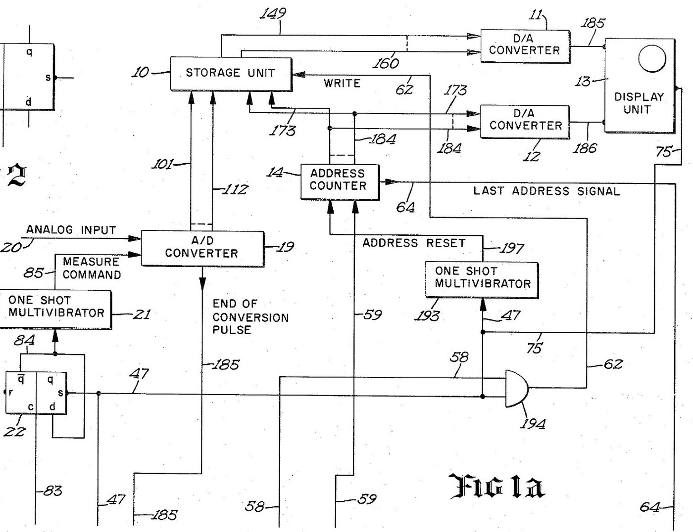


Digital Oscilloscope: Waveform Stored in Memory and Shown on a CRT (Schumann, Nicolet, US 3,816,815, 1974)
An oscilloscope with a memory. After a trigger, an analog-to-digital converter measures the input at regular intervals and writes each reading into its own memory register, replacing the old one. The screen then shows the memory: each register's number sets the beam's height, its address sets the beam's place across. The last waveform can be held on the screen as long as you like.
Result: a digital storage oscilloscope with 4,096 points of 12 bits, refresh and hold modes and single-shot capture.
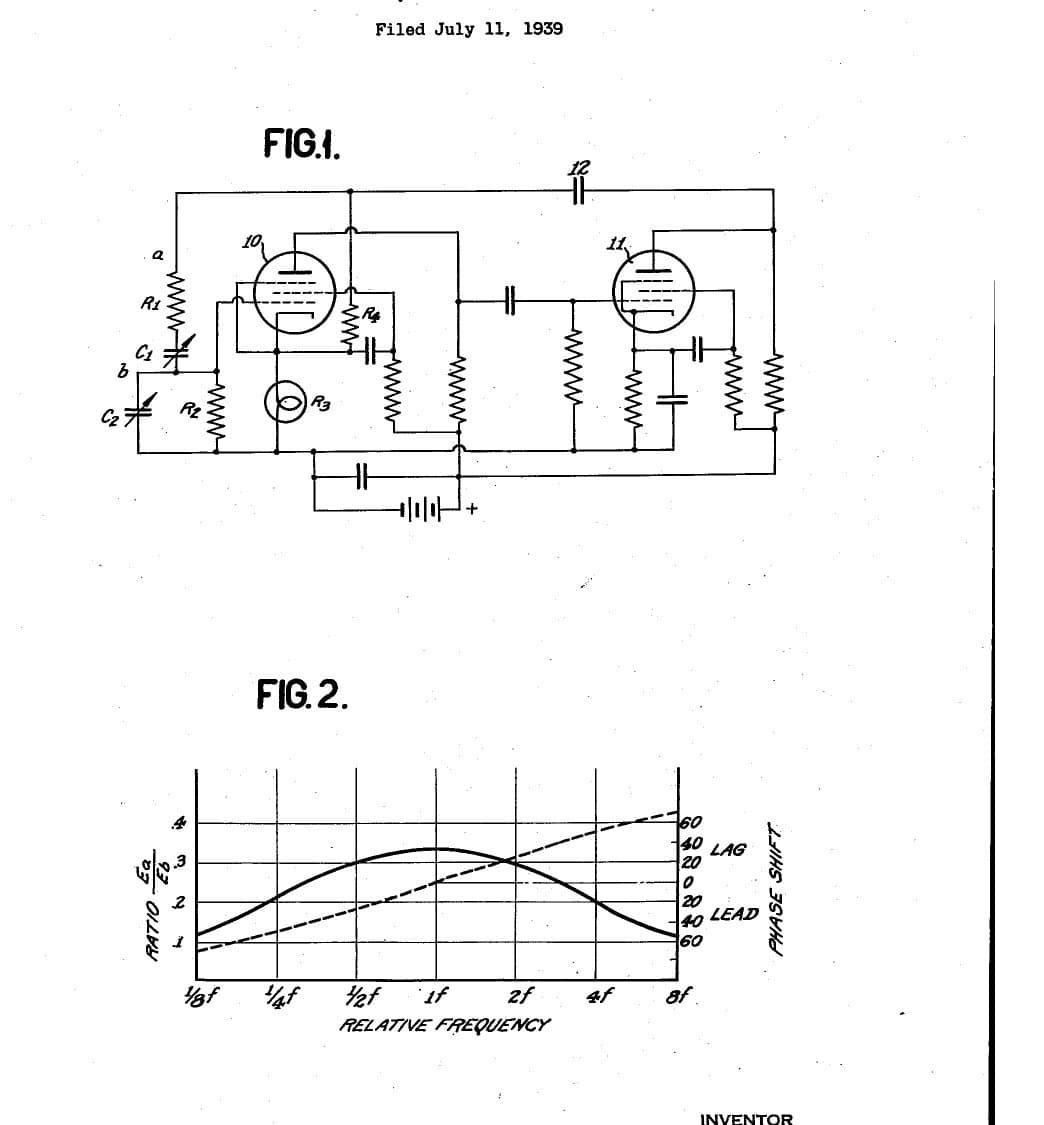
Source: R. W. Schumann (Nicolet), US 3,816,815 (1974). Unknown: sample rate, bandwidth, voltages and the parts used. Picture: the patent drawing.
Expert
Unknown
Instructions
1
1
Sample and convert the input
Sample and convert the input
Bring the analog input to an analog-to-digital converter, through a BNC socket. A sampling oscillator, divided by four by two flip-flops so the first reading comes soon after the sweep starts, fires a one-shot multivibrator that gives the converter its measure command. The converter holds each 12-bit result on its output lines and signals the end of each conversion. Ours: a BNC socket. Not given: the sample rate.
Materials for this step:
 Analog-to-Digital Converter1 12-bit converter
 Clock Oscillator1 sampling oscillator
 Logic IC Assortment1 flip-flops, one-shots, gates
 Coaxial Connector Set (BNC / SO-239)1 input socket
Tools needed:
 Soldering Iron
 Wire Strippers
2
2
Store each reading in memory
Store each reading in memory
Wire an integrated-circuit memory of 4,096 registers, 12 bits each, that can be read without changing it. A 12-bit address counter picks the register. On each write command the register at the current address takes the last reading from the converter, and the counter steps on. When the sweep starts, a one-shot resets the counter to zero. When it reaches the last address, its last-address signal ends the sweep.
Materials for this step:
 Integrated-Circuit Memory1 4,096 x 12-bit store
Tools needed:
Soldering IronWire Strippers3
3
Drive the CRT from the memory
Drive the CRT from the memory
Feed the addressed register's number to one digital-to-analog converter and the address to a second. Their outputs drive the vertical and horizontal deflection plates of a cathode-ray tube, so the beam always stands at the height of the stored reading and at the place of its address. Wire the sweep line to the tube's intensifier, to brighten the trace while a waveform is being taken.
Materials for this step:
 Digital-to-Analog Converter2 vertical and horizontal
 Cathode-Ray Tube1 display tube
Tools needed:
Soldering IronWire Strippers4
4
Wire the trigger and the modes
Wire the trigger and the modes
A trigger input, usually from the leading edge of the input waveform, starts the sweep, once a measure flip-flop has armed it. Put a two-position mode switch on the face: MODE I and MODE II. Add a push button in the probe, a switch on the panel and an external initiate input; each goes through a flip-flop that removes contact bounce. Two more oscillators step the memory round to refresh the display between waveforms. Mount it all in a case with its supply. Ours: toggle switches, an aluminium case, a DC supply. Not given: the supply voltages.
Materials for this step:
Clock Oscillator2 display sequencing oscillators Toggle Switch2 mode and panel switches
 Push Button1 probe switch
 Aluminium Enclosure Box1 case
Tools needed:
 DC Power Supply
 Drill PressSoldering Iron
5
5
Capture and hold a waveform
Capture and hold a waveform
In MODE I, refresh: each new triggered waveform replaces the last on the screen. Press the probe or panel switch to hold: new waveforms are rejected and the last one stays on the screen. In MODE II the screen normally holds; on command, it takes the first waveform after the command, stores it and shows it steadily. Test it with a known signal.
Tools needed:
 Function Generator
Materials
10- 1 12-bit converterPlaceholder
- 2 display sequencing oscillatorsPlaceholder
- 1 flip-flops, one-shots, gatesPlaceholder
- 1 input socketPlaceholder
- 1 4,096 x 12-bit storePlaceholder
- 2 vertical and horizontalPlaceholder
- 1 display tubePlaceholder
- Placeholder
- Placeholder
- 1 casePlaceholder
Tools Required
5- 2 vendors sell this, none ship to you yetPlaceholder
- Placeholder
- Placeholder
- Placeholder
- Placeholder
This blueprint makes

Related Blueprints
These blueprints share knowledge with this one — techniques, materials, or principles that connect them in the learning graph.
CC0 Public Domain
This blueprint is released under CC0. You are free to copy, modify, distribute, and use this work for any purpose, without asking permission.
Support the Maker by purchasing products through their Blueprint where they earn a Maker Commission set by Vendors, or create a new iteration of this Blueprint and include it as a connection in your own Blueprint to share revenue.