ART
BEAUTY & WELLNESS
CRAFT
CULTURE & HISTORY
ENTERTAINMENT
ENVIRONMENT
FOOD & DRINKS
REVERSE ENGINEERING
SCIENCES
SPORTS
TECHNOLOGY
WEARABLES
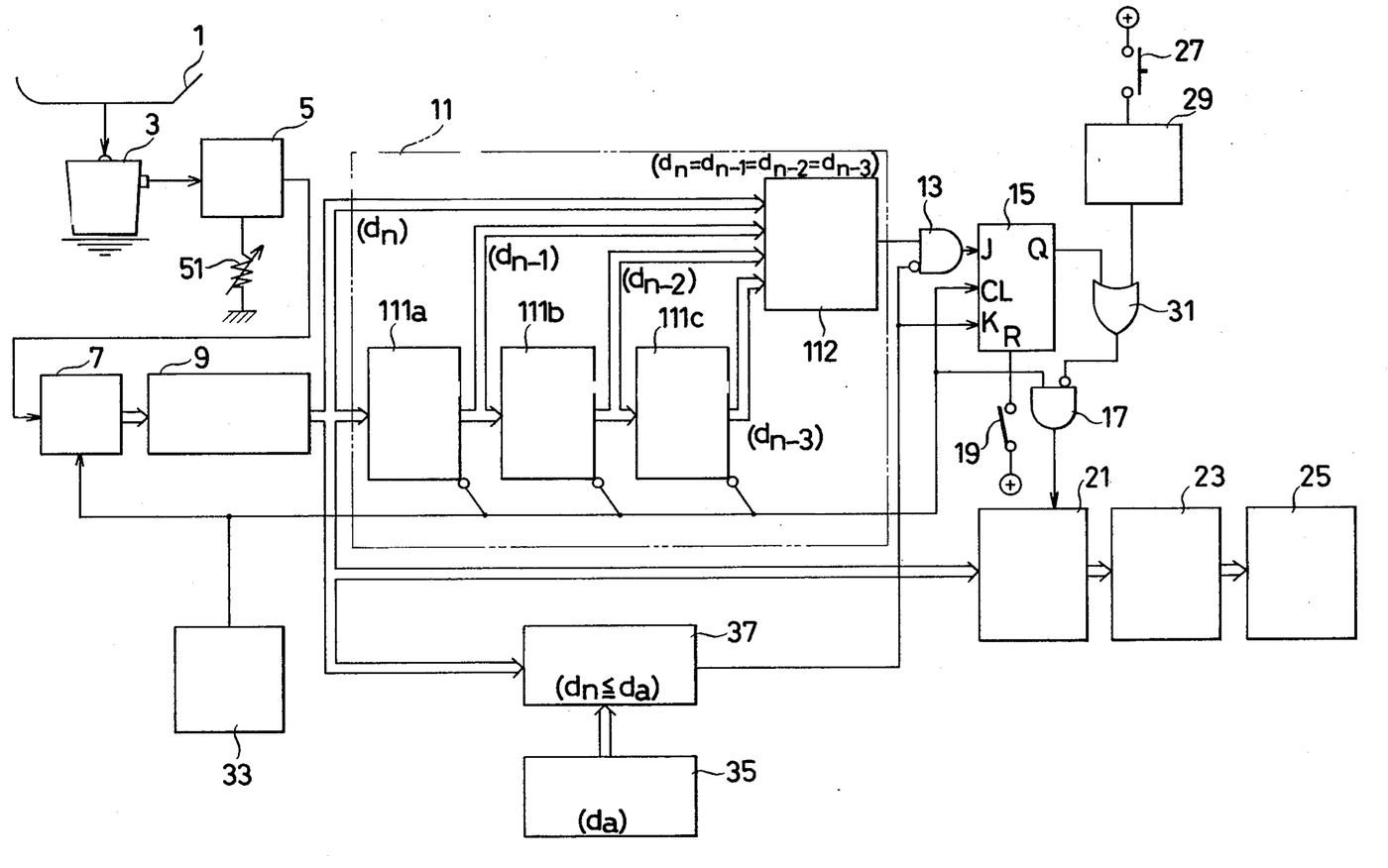


Electronic Baby Scale That Holds a Steady Reading: Hino & Itani, 1981
Masamichi Hino and Seiichi Itani of Kubota Ltd., Osaka, patented this electronic weighing apparatus in 1981, US 4,285,411. A strain-gauge load cell barely moves, so a baby on the pan is not frightened, but babies seldom lie still and the displayed weight keeps changing. Here the scale keeps showing each new reading until it has stopped changing, then holds that weight on a four-digit display until the baby is lifted off. The patent names baby scales in hospitals, and also price computing scales.
Advanced
Factory process
Instructions
1
1
Pan and load cell
Pan and load cell
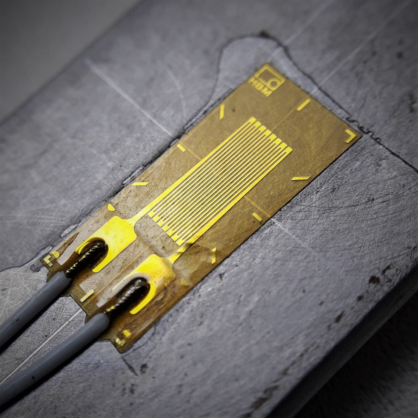
Couple the article placing pan, such as a basket for a baby, mechanically to a strain-gauge load cell in the casing. The load cell gives an analog voltage that follows the weight on the pan; an amplifier, its gain set by a variable resistor, raises it.
Materials for this step:
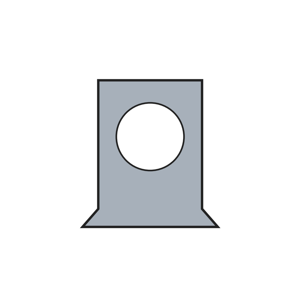 Scale Casing1 piece
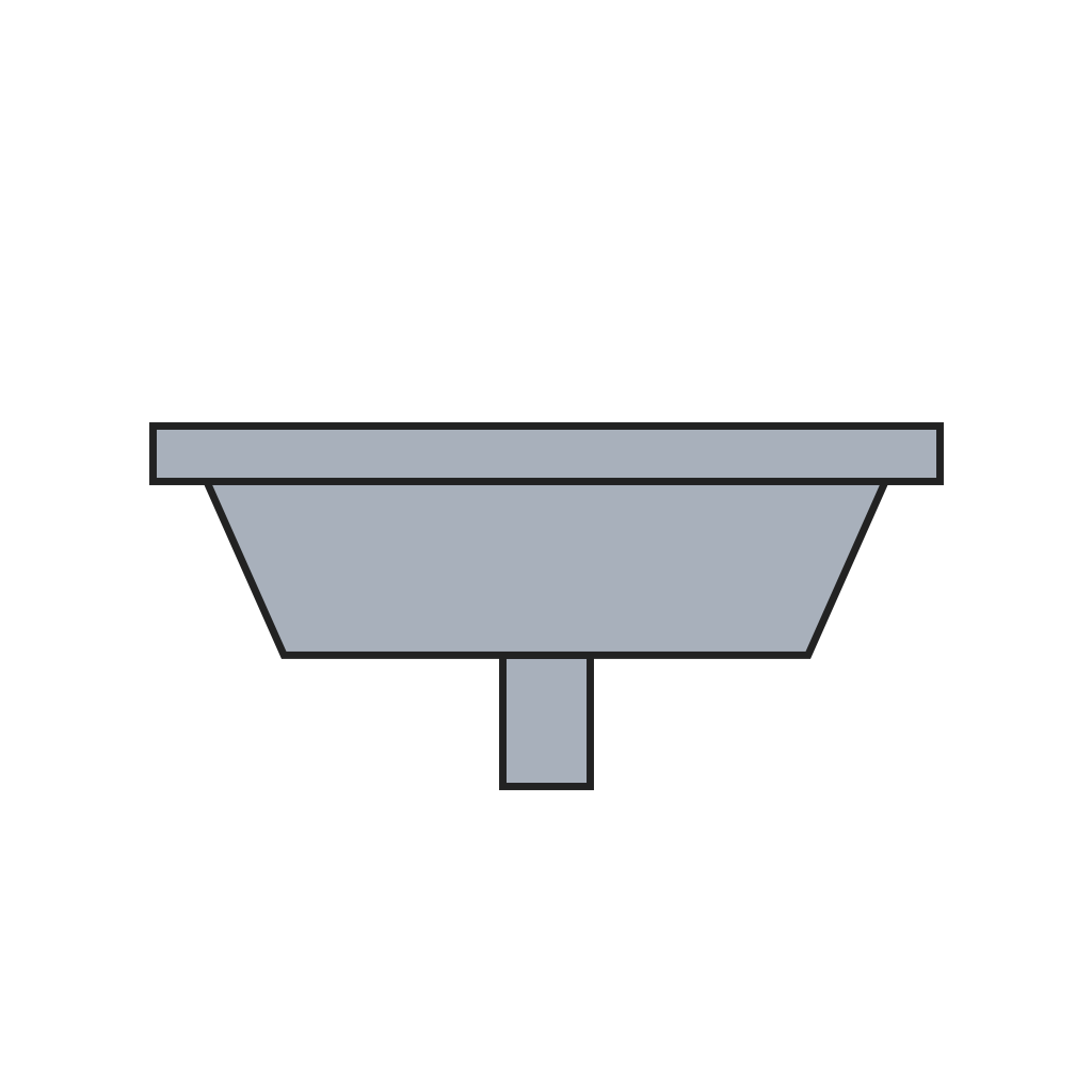 Weighing Pan1 piece
 Load Cell1 piece
 Load Cell Amplifier1 piece
 Potentiometer1 piece
 Hookup Wire1 as required
 Solder Wire1 as required
Tools needed:
 Electric Soldering Iron
2
2
Convert to digital
Convert to digital
An analog-to-digital converter turns the amplified voltage into digital data at each pulse from a timing pulse generator.
Materials for this step:
 Analog-to-Digital Converter1 piece
 Timing Pulse Generator1 piece
Tools needed:
Electric Soldering Iron3
3
Span adjustment
Span adjustment
Pass the data through a digital multiplier. Set the variable resistor so the span is slightly too large, then set a multiplier below 0.9999 on the numerical value setting switch (its two upper digits are fixed at 9, the two lower ones are set) until a known rated weight on the pan reads correctly. The resistor gives the coarse adjustment, the switch the fine one; digital multiplication is not upset by temperature or humidity.
Materials for this step:
 Digital Multiplier1 piece
 Numerical Value Setting Switch1 piece
Tools needed:
Electric Soldering Iron Weight
4
4
Stable-state detector
Stable-state detector
Feed the data into three registers in cascade that shift it on at each timing pulse, so they hold the three previous readings. A coincidence detecting circuit (exclusive-NOR and AND gates) gives a high output when the newest reading equals all three: the weight is steady. (A second version subtracts the previous reading from the newest and calls it steady when the difference is within a set value, which may be zero.)
Materials for this step:
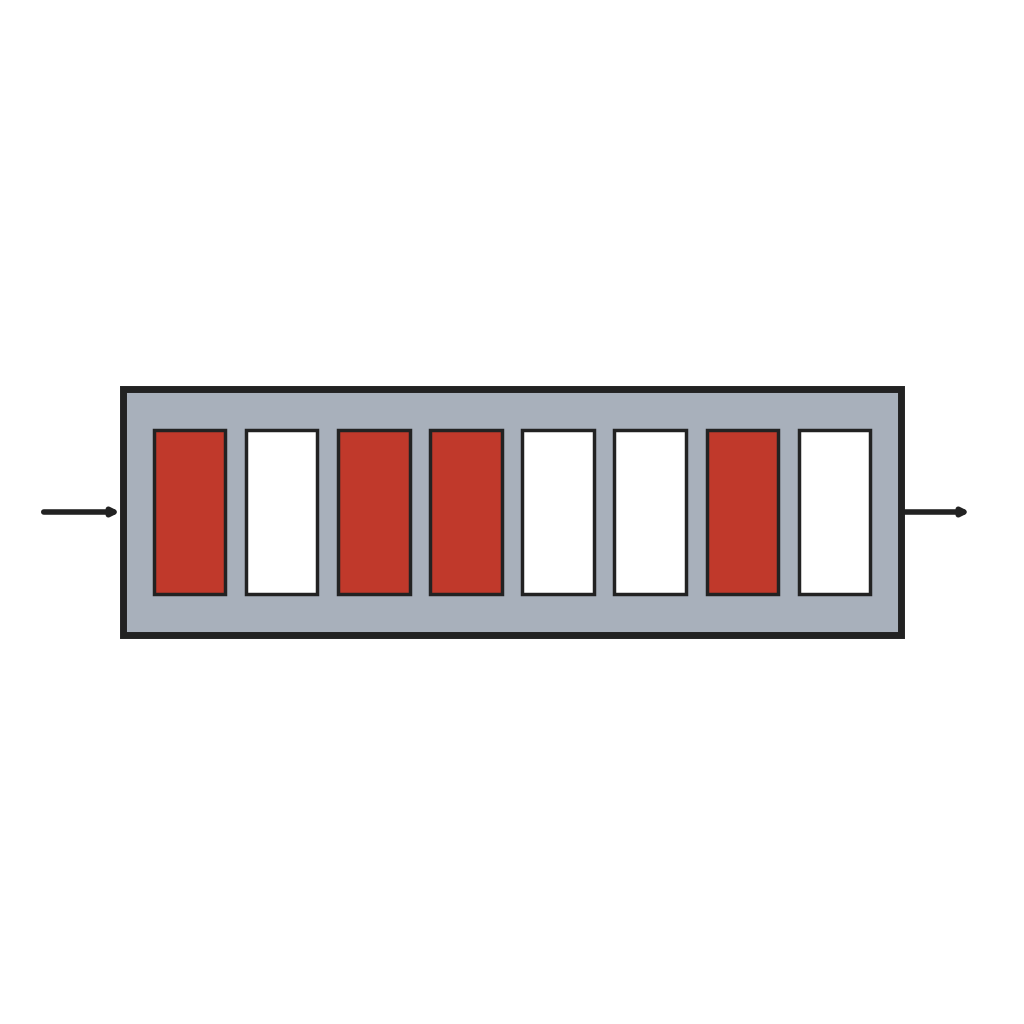 Digital Data Register3 pieces
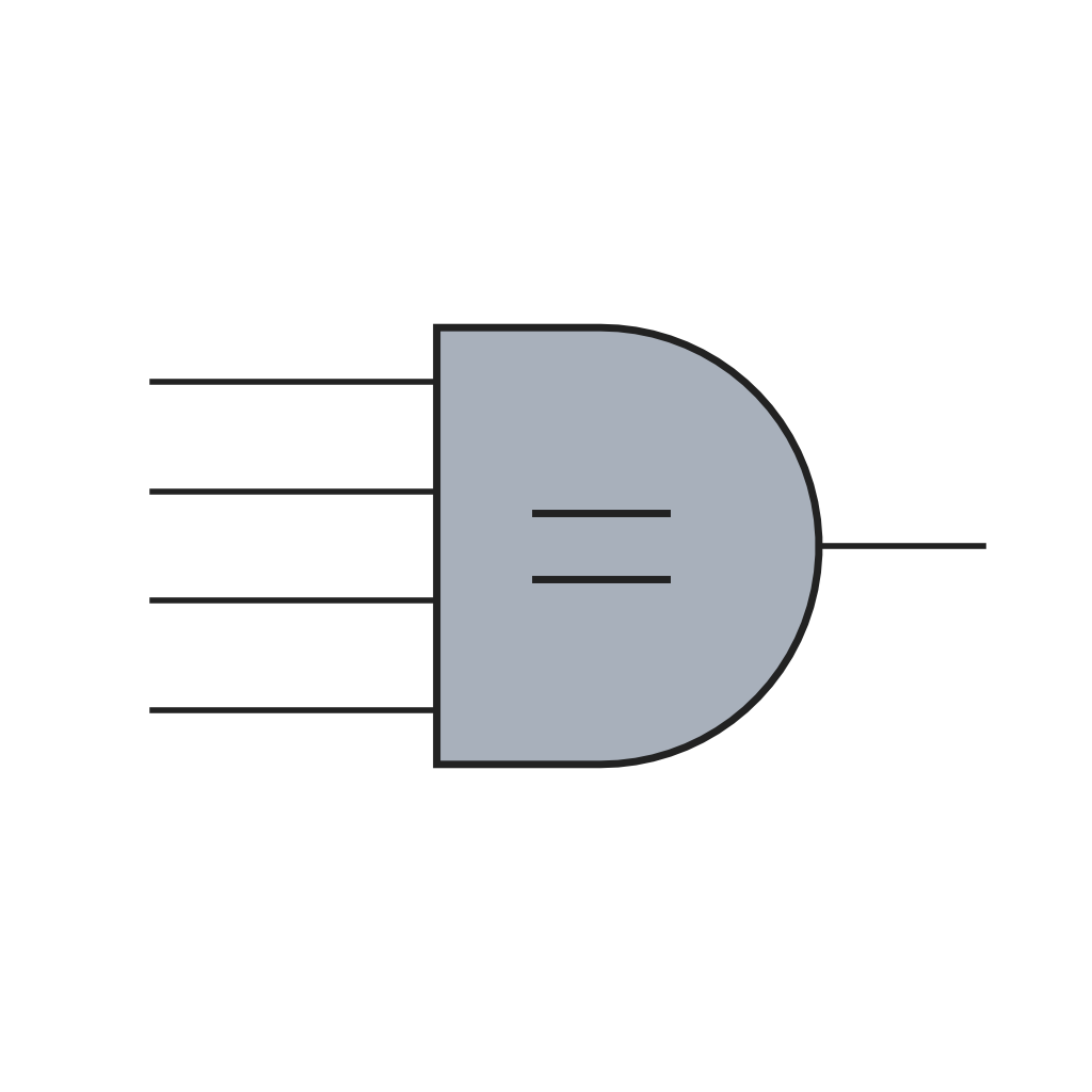 Coincidence Detecting Circuit1 piece
Tools needed:
Electric Soldering Iron5
5
Hold the reading
Hold the reading
Load the display buffer with each new reading through an inhibit gate. When the detector reports a steady weight, it sets a J-K flip-flop; the flip-flop's output, through an OR gate, closes that inhibit gate, so the buffer keeps the steady weight even if the baby moves. A digital comparator checks each new reading against a reference value, for example 2 grams: when the baby is lifted off and the reading falls to it, the flip-flop resets and the display follows the new readings again. No button is needed to release the hold.
Materials for this step:
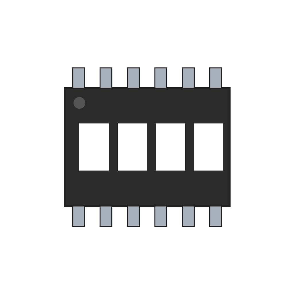 Display Buffer1 piece
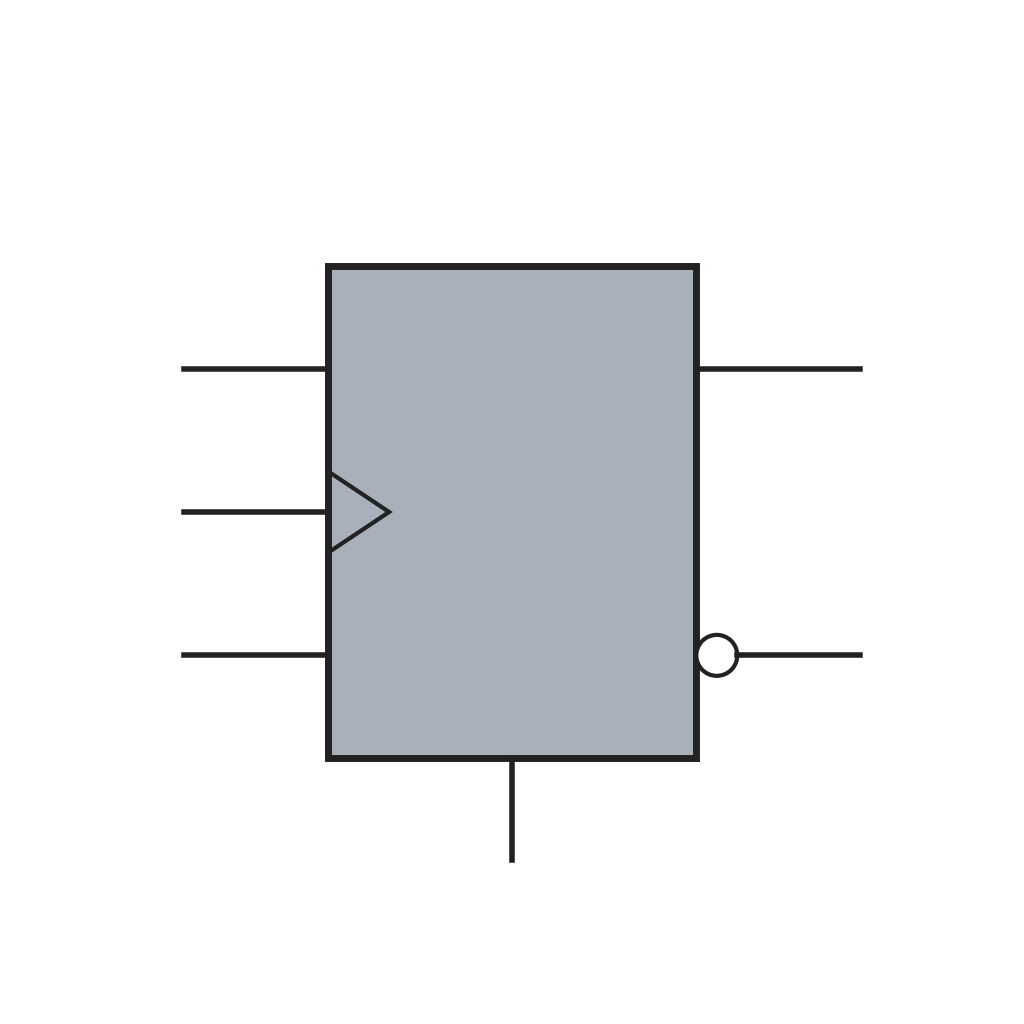 J-K Flip-Flop1 piece
 Logic Gate3 pieces
 Digital Comparator1 piece
 Reference Value Setting Circuit1 piece
Tools needed:
Electric Soldering Iron6
6
Display and switches
Display and switches
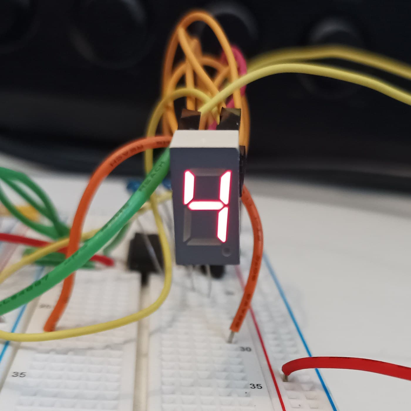
Drive a four-digit display of seven-segment numerals from the buffer through a segment decoder. Fit two switches outside the casing: one keeps the flip-flop reset, so the newest weight is always shown; the other starts a timer that freezes the display for a set time, say eight seconds, so the weight can be read and written down without a mistake.
Materials for this step:
 Seven-Segment Display Driver1 piece
 Four-Digit Seven-Segment Display1 piece
 On/Off Switch2 pieces
 Display Hold Timer1 piece
Tools needed:
Electric Soldering IronMaterials
22- 1 piecePlaceholder
- 1 piecePlaceholder
- 1 piecePlaceholder
- 1 piecePlaceholder
- Placeholder
- 1 as requiredPlaceholder
- 1 as requiredPlaceholder
- 1 piecePlaceholder
- 1 piecePlaceholder
- 1 piecePlaceholder
- Placeholder
- 3 piecesPlaceholder
- Placeholder
- 1 piecePlaceholder
- 1 piecePlaceholder
- 3 piecesPlaceholder
- 1 piecePlaceholder
- Placeholder
- 1 piecePlaceholder
- Placeholder
- 2 piecesPlaceholder
- 1 piecePlaceholder
This blueprint makes

Related Blueprints
These blueprints share knowledge with this one — techniques, materials, or principles that connect them in the learning graph.



CC0 Public Domain
This blueprint is released under CC0. You are free to copy, modify, distribute, and use this work for any purpose, without asking permission.
Support the Maker by purchasing products through their Blueprint where they earn a Maker Commission set by Vendors, or create a new iteration of this Blueprint and include it as a connection in your own Blueprint to share revenue.