"""Worm and helical worm wheel, module 1 (ours), for batch 2525. Imported by build_all.py and check.py."""
import math
import FreeCAD as App, Part
V = App.Vector
M = 1.0                    # axial module of the worm = transverse module of the wheel
PA = math.radians(20)      # pressure angle
WORM_PD = 10.0             # worm pitch diameter
WORM_L = 14.0
Z_WHEEL = 30
WHEEL_B = 6.0              # wheel face width
BACKLASH = 0.15            # mm taken off each tooth flank pair (printed parts)
LEAD = math.pi * M         # single start: lead = axial pitch
LAMBDA = math.atan(LEAD / (math.pi * WORM_PD))   # lead angle
CENTRE = (WORM_PD + Z_WHEEL * M) / 2

def worm(bore=2.9, per_turn=24, n_theta=180):
    """Single-start worm, axis = z from 0 to WORM_L. Built from its transverse section (exact for the straight-sided axial
    profile): at angle t the thread is met at axial position u = z + t*LEAD/(2 pi); the section is that radius curve, and the
    worm is the section turned by -360 deg per lead, lofted (ruled) through per_turn sections a turn."""
    rp = WORM_PD / 2
    ra, rf = rp + M, rp - 1.25 * M
    p = LEAD
    ht = (p / 4 - M * math.tan(PA)) - BACKLASH / 2      # half tooth width (axial) at the tip
    hr = (p / 4 + 1.25 * M * math.tan(PA)) - BACKLASH / 2  # ... at the root
    def R(t):
        u = (t * p / (2 * math.pi)) % p
        u = min(u, p - u)                                 # distance from the tooth centre
        if u <= ht: return ra
        if u >= hr: return rf
        return rf + (hr - u) / (hr - ht) * (ra - rf)
    base = [(R(2 * math.pi * i / n_theta), 2 * math.pi * i / n_theta) for i in range(n_theta)]
    zs = [-p / per_turn * 2]
    while zs[-1] < WORM_L + p / per_turn * 2:
        zs.append(zs[-1] + p / per_turn)
    wires = []
    for z in zs:
        rot = -2 * math.pi * z / p
        P = [V(r * math.cos(t + rot), r * math.sin(t + rot), z) for r, t in base]
        wires.append(Part.makePolygon(P + [P[0]]))
    w = Part.makeLoft(wires, True, True)
    c = ra - rf                                    # 45 degree chamfer at both ends: the thread does not end in a knife edge
    env = Part.Face(Part.makePolygon([V(0, 0, 0), V(rf, 0, 0), V(ra, 0, c), V(ra, 0, WORM_L - c), V(rf, 0, WORM_L), V(0, 0, WORM_L), V(0, 0, 0)])).revolve(V(0, 0, 0), V(0, 0, 1), 360)
    w = w.common(env)
    w = w.cut(Part.makeCylinder(bore / 2, WORM_L + 2, V(0, 0, -1)))
    return w

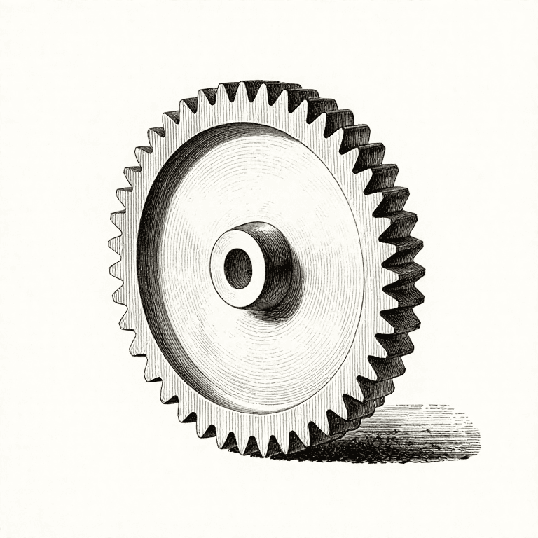
def involute_profile(z, m, pts=12):
    """2D closed polygon of a spur gear (involute flanks, root arc), centred at the origin."""
    rp = z * m / 2; rb = rp * math.cos(PA); ra = rp + m; rf = rp - 1.25 * m
    inv = lambda a: math.tan(a) - a
    tooth_half_ang = (math.pi / (2 * z)) + inv(PA) - (BACKLASH / 2) / rp   # half tooth angle at the base circle
    def flank(sign):
        out = []
        for i in range(pts + 1):
            r = rb + (ra - rb) * i / pts
            r = max(r, rb)
            a = math.acos(min(1.0, rb / r))
            th = tooth_half_ang - inv(a)
            out.append((r, sign * th))
        return out
    poly = []
    for k in range(z):
        c = 2 * math.pi * k / z
        left = flank(-1); right = flank(1)
        r0 = max(rf, 0.1)
        poly.append((r0, c - tooth_half_ang - 0.02))
        poly += [(r, c + th) for r, th in left]
        poly += [(r, c + th) for r, th in reversed(right)]
        poly.append((r0, c + tooth_half_ang + 0.02))
        # root land to the next tooth
        nxt = 2 * math.pi * (k + 1) / z - tooth_half_ang - 0.02
        for j in range(1, 4):
            poly.append((rf, c + tooth_half_ang + 0.02 + (nxt - (c + tooth_half_ang + 0.02)) * j / 4))
    return [(r * math.cos(t), r * math.sin(t)) for r, t in poly]

def wheel(bore=3.9):
    """Helical wheel: profile lofted with the twist of a helix at the worm's lead angle (axis = z, 0..WHEEL_B)."""
    rp = Z_WHEEL * M / 2
    twist = WHEEL_B * math.tan(LAMBDA) / rp        # radians over the face width
    pts = involute_profile(Z_WHEEL, M)
    def wire(zz, rot):
        c, s = math.cos(rot), math.sin(rot)
        P = [V(x * c - y * s, x * s + y * c, zz) for x, y in pts]
        return Part.makePolygon(P + [P[0]])
    n = 4
    wires = [wire(WHEEL_B * i / n, twist * i / n) for i in range(n + 1)]
    g = Part.makeLoft(wires, True, True)
    g = g.cut(Part.makeCylinder(bore / 2, WHEEL_B + 2, V(0, 0, -1)))
    g = g.mirror(V(0, 0, 0), V(1, 0, 0))        # helix hand that meshes with this worm (found by check.py: 0 overlap)
    return g, math.degrees(twist)

MESH_PHASE = 4.0          # wheel angle (deg) at worm angle 0 for a clean mesh, axis set-up as in check.py


# ---- build_all.py ----
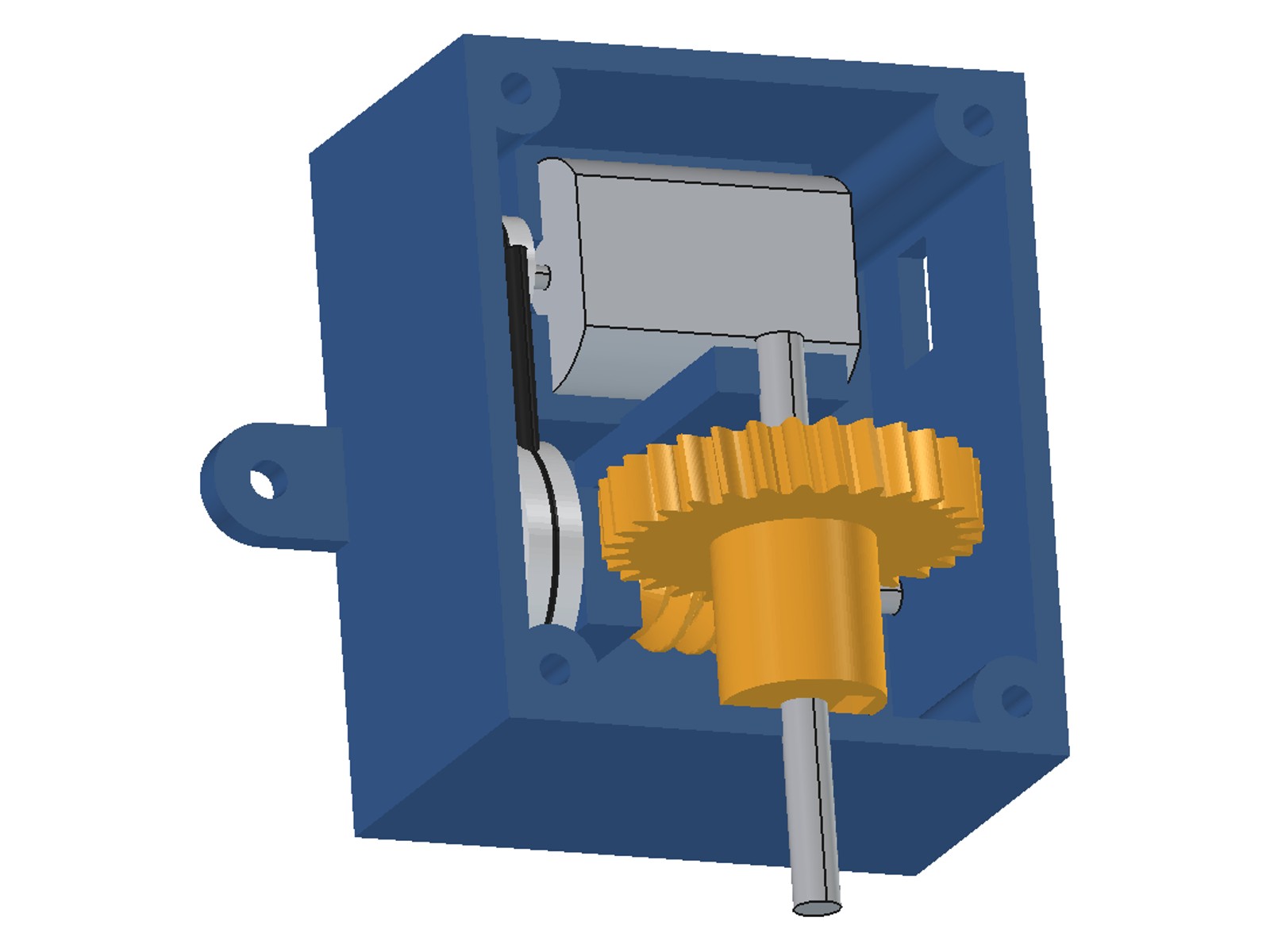
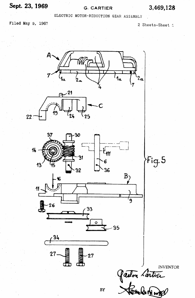
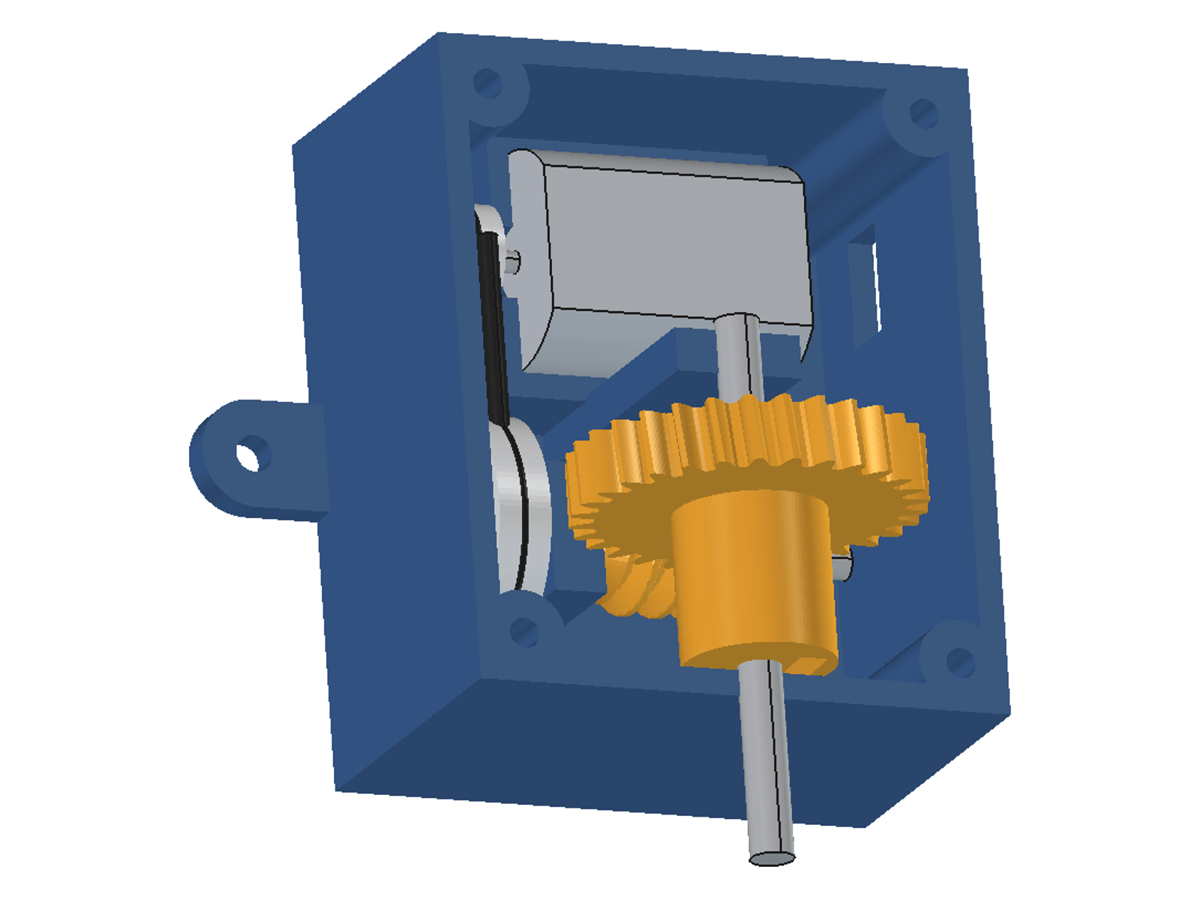
"""Batch 2525 -- printed worm gearmotor after Cartier (US 3,469,128, 1969): a small DC motor (Mabuchi FA-130 size: can 20.1 mm,
15.1 mm over the flats, 25 mm long, 2 mm shaft standing 9.4 mm out, front boss 6.15 mm) drives a worm shaft parallel to it by a
belt (an O-ring); the worm turns a wheel on an output shaft at right angles; the output shaft's bearings are half in the base
and half in the cap, as in his claim 1. ALL sizes ours. Parts (each printed flat face down, no supports):
  gm-base     motor cradle, two worm-shaft bearings, the lower halves of the output-shaft bearings, 4 screw posts, 2 mounting lugs
  gm-cap      the upper halves; clamps the motor; 4 x M3 x 30 through the cap into the posts
  gm-worm     single start, module 1, 10 mm pitch diameter, on a 3 mm shaft
  gm-wheel    30 teeth, helical at the worm's lead angle, hub with an M3 nut slot and set screw, on a 4 mm shaft
  gm-pulley-small / gm-pulley-large   6 and 18 mm groove diameters for a 1.9 mm O-ring
Run: OUT=<dir> freecadcmd build_all.py   (mm). Mesh check: freecadcmd check.py"""
import math, os, sys
sys.path.insert(0, os.path.dirname(os.path.abspath(__file__)))
import FreeCAD as App, Part, MeshPart
import gears as G
OUT = os.environ["OUT"]
V = App.Vector
WALL, FLOOR = 2.4, 3.0
ZW = 13.0                        # worm and motor axis height
ZO = ZW + G.CENTRE               # output shaft axis height = split plane between base and cap
X0, X1, Y0, Y1 = -27.0, 24.0, -20.0, 40.0   # case outside (x to 24: motor terminals and the worm shaft end clear the posts and wall)
MOTOR_Y = 26.0                   # motor axis, parallel to the worm (x), 26 mm to the side
MOTOR_FRONT_X = -12.0            # face of the motor's front boss; the body runs +x for 25 mm
CAN_D, CAN_FLAT, CAN_L = 20.1, 15.1, 25.0
PULLEY_X = -17.5                 # both pulleys centred here
BRG = [(-12.5, -7.5), (7.5, 12.5)]   # worm-shaft bearing pillars (x ranges); worm x -7..7
OUT_PILLAR_Y = (10.0, 14.0)      # inner output-shaft bearing pillar
CAP_TOP = ZO + G.Z_WHEEL / 2 + G.M + 2.5 + 2.4

def save(sh, name):
    sh = sh.removeSplitter()
    bb = sh.BoundBox
    print(name, "valid", sh.isValid(), "solids", len(sh.Solids), "bbox", [round(v, 1) for v in (bb.XLength, bb.YLength, bb.ZLength)],
          "volume_cm3", round(sh.Volume / 1000, 2))
    if not os.environ.get("NOSAVE"):
        MeshPart.meshFromShape(Shape=sh, LinearDeflection=0.02, AngularDeflection=0.1).write(os.path.join(OUT, name + ".stl"))
    return sh

def box(x0, x1, y0, y1, z0, z1):
    return Part.makeBox(x1 - x0, y1 - y0, z1 - z0, V(x0, y0, z0))

def ycyl(r, y0, y1, x, z):
    return Part.makeCylinder(r, y1 - y0, V(x, y0, z), V(0, 1, 0))

def xcyl(r, x0, x1, y, z):
    return Part.makeCylinder(r, x1 - x0, V(x0, y, z), V(1, 0, 0))

POSTS = [(X0 + 4.5, Y0 + 4.5), (X1 - 4.5, Y0 + 4.5), (X0 + 4.5, Y1 - 4.5), (X1 - 4.5, Y1 - 4.5)]

# ---------------- base: tray up to the split plane ZO
base = box(X0, X1, Y0, Y1, 0, ZO).cut(box(X0 + WALL, X1 - WALL, Y0 + WALL, Y1 - WALL, FLOOR, ZO + 1))
# worm-shaft bearing pillars (3.1 mm bores = running fit on a 3 mm shaft) up to ZW + 5 (the wheel rim passes 0.9 mm above)
for (a, b) in BRG:
    base = base.fuse(box(a, b, -6, 6, FLOOR, ZW + 5)).cut(xcyl(1.55, a - 1, b + 1, 0, ZW))
# motor cradle: a block with the can's shape cut in, from the boss face to the rear
cradle = box(MOTOR_FRONT_X - 2.0, MOTOR_FRONT_X + CAN_L, MOTOR_Y - 12.5, MOTOR_Y + 12.5, FLOOR, ZW)
can = xcyl(CAN_D / 2 + 0.15, MOTOR_FRONT_X, MOTOR_FRONT_X + CAN_L + 5, MOTOR_Y, ZW).common(box(-60, 60, MOTOR_Y - 20, MOTOR_Y + 20, ZW - CAN_FLAT / 2 - 0.15, ZW + CAN_FLAT / 2 + 0.15))
base = base.fuse(cradle).cut(can)
base = base.cut(xcyl(3.3, MOTOR_FRONT_X - 2.5, MOTOR_FRONT_X + 0.1, MOTOR_Y, ZW))          # 6.15 mm boss locates in a 6.6 mm hole
base = base.cut(xcyl(2.0, MOTOR_FRONT_X - 3, MOTOR_FRONT_X, MOTOR_Y, ZW))                 # shaft clearance
# inner output-shaft pillar and the lower half of both output bearings (4.1 mm = running fit on 4 mm)
base = base.fuse(box(-6, 6, OUT_PILLAR_Y[0], OUT_PILLAR_Y[1], FLOOR, ZO))
base = base.cut(ycyl(2.05, Y0 - 1, OUT_PILLAR_Y[1] + 0.01, 0, ZO))
# screw posts (2.8 mm pilots for M3, 18 mm deep) and two mounting lugs with 3.4 mm holes
for (x, y) in POSTS:
    base = base.fuse(Part.makeCylinder(4.0, ZO - FLOOR, V(x, y, FLOOR))).cut(Part.makeCylinder(1.4, 19, V(x, y, ZO - 18)))
for x in (X0 - 7, X1 + 7):
    lug = box(min(x, x + (7 if x < 0 else -7)), max(x, x + (7 if x < 0 else -7)), 5, 15, 0, 3).fuse(Part.makeCylinder(5, 3, V(x, 10, 0)))
    base = base.fuse(lug).cut(Part.makeCylinder(1.7, 5, V(x, 10, -1)))
# recess in the floor under the large pulley (its rim hangs 0.9 mm below the floor top), 1 mm floor left
base = base.cut(box(PULLEY_X - 3.5, PULLEY_X + 3.5, -12.5, 12.5, 1.0, FLOOR + 0.1))
# wire slot behind the motor, through the rear wall
base = base.cut(box(X1 - WALL - 1, X1 + 1, MOTOR_Y - 5, MOTOR_Y + 5, ZW - 3, ZW + 3))
base = save(base, "gm-base")

# ---------------- cap: from ZO up, walls matching the base, upper bearing halves, presses on the motor's top flat
cap = box(X0, X1, Y0, Y1, ZO, CAP_TOP).cut(box(X0 + WALL, X1 - WALL, Y0 + WALL, Y1 - WALL, ZO - 1, CAP_TOP - 2.4))
cap = cap.fuse(box(-6, 6, OUT_PILLAR_Y[0], OUT_PILLAR_Y[1], ZO, CAP_TOP - 2.4))
cap = cap.cut(ycyl(2.05, Y0 - 1, OUT_PILLAR_Y[1] + 0.01, 0, ZO))
cap = cap.fuse(box(MOTOR_FRONT_X + 3, MOTOR_FRONT_X + CAN_L - 3, MOTOR_Y - 6, MOTOR_Y + 6, ZW + CAN_FLAT / 2, CAP_TOP))   # motor clamp: rests on the can's top flat
for (x, y) in POSTS:
    cap = cap.fuse(Part.makeCylinder(4.0, CAP_TOP - ZO, V(x, y, ZO)))
    cap = cap.cut(Part.makeCylinder(1.7, 30, V(x, y, ZO - 1))).cut(Part.makeCylinder(3.2, 4, V(x, y, CAP_TOP - 3)))
cap = save(cap, "gm-cap")

# ---------------- gears and pulleys (saved in printing position)
worm = save(G.worm(), "gm-worm")
wheel, twist = G.wheel()
# hub reaches the outer wall (wheel centred 3 mm from the axis plane; wall inner face 17.6 mm out): it locates the wheel and shaft
HUB_L = (-Y0 - WALL) - G.WHEEL_B / 2 - 0.5
hub = Part.makeCylinder(7.0, HUB_L, V(0, 0, G.WHEEL_B)).cut(Part.makeCylinder(1.95, 40, V(0, 0, -1)))
SS_Z = G.WHEEL_B + HUB_L - 4.0
hub = hub.cut(Part.makeCylinder(1.7, 8, V(0, 0, SS_Z), V(1, 0, 0)))                 # radial M3 hole, 4 mm from the hub end
hub = hub.cut(box(2.8, 5.4, -2.9, 2.9, SS_Z - 2.85, G.WHEEL_B + HUB_L + 0.1))   # nut centred on the hole                    # M3 nut slot (5.5 AF, 2.4 thick) from the hub end
wheel = save(wheel.fuse(hub), "gm-wheel")
def pulley(groove_d, width, bore):
    r_out = groove_d / 2 + 1.9
    p = Part.makeCylinder(r_out, width)
    groove = Part.makeTorus(groove_d / 2 + 0.95, 0.95 + 0.05, V(0, 0, width / 2))
    return p.cut(groove).cut(Part.makeCylinder(bore / 2, width + 2, V(0, 0, -1)))
psmall = save(pulley(6.0, 5.0, 1.9), "gm-pulley-small")      # press fit on the 2 mm motor shaft
plarge = save(pulley(18.0, 5.0, 2.9), "gm-pulley-large")     # press fit on the 3 mm worm shaft

print("lead angle", round(math.degrees(G.LAMBDA), 2), "deg; centre distance", G.CENTRE, "mm; wheel twist", round(twist, 2), "deg over", G.WHEEL_B, "mm")
print("worm/motor axis z", ZW, "; output axis z", ZO, "; cap top z", round(CAP_TOP, 1))
print("motor can: bottom flat at z", round(ZW - CAN_FLAT / 2, 2), "(floor", FLOOR, ") ; side at y", MOTOR_Y - CAN_D / 2, "(worm pillar edge y 6)")
print("large pulley edge y", 9 + 1.9, "; motor can near side y", MOTOR_Y - CAN_D / 2, "; motor pulley x", PULLEY_X, "on shaft from", MOTOR_FRONT_X - 1.7, "to", MOTOR_FRONT_X - 9.4 - 0)

 PETG Filament45 g
 FDM 3D Printer
 Digital Caliper 6-Inch
 Stainless Steel Rod2 piece (3 mm x 40 mm, 4 mm x 50 mm)
 Hacksaw
 Metal File
 Electric Motor1 piece (FA-130 size, 3 V)
 O-Ring1 piece (24 x 1.9 mm)
 Hookup Wire0.3 m
 Solder Wire1 g
 Soldering Iron
 Hex Nut1 piece (M3)
 Cup Point Set Screw1 piece (M3 x 6)
 Shaft Collar1 piece (4 mm bore)
 Socket Head Cap Screw4 piece (M3 x 30)
 Hex Key Set
 Battery Holder
 Battery