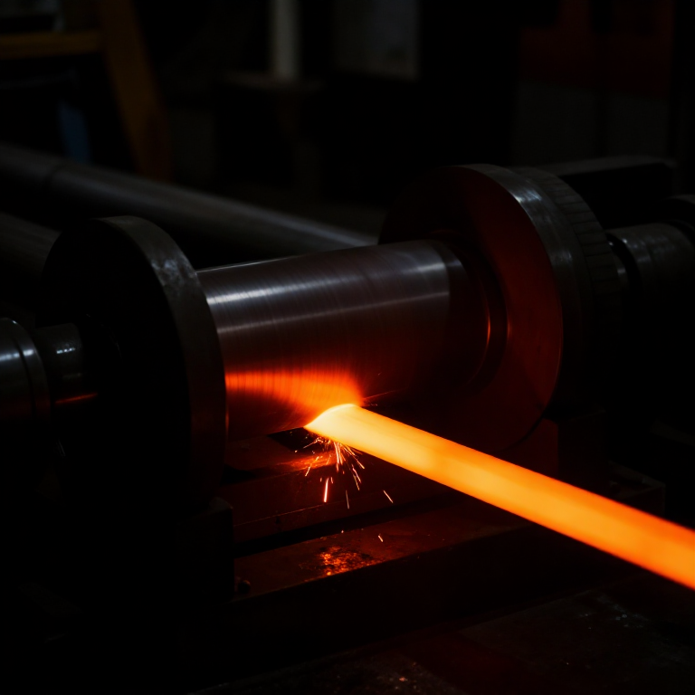


Grooved Rolling Mill
Instructions
Make the roll pair and their housing
Make the roll pair and their housing
Two rolls, geared together, in a frame stiff enough to resist being pushed apart.
- Turn two rolls 80 mm diameter, 120 mm long, from aluminium round bar.
- Mount each in two 608 bearings in a plywood housing.
- Set the roll axes parallel and in the same vertical plane, checked with the caliper at both ends.
- Fix the housing with M6 × 50 hex bolts × 6, M6 flat washers × 12 and M6 hex nuts × 6.
- Gear the rolls together so they counter-rotate at equal speed.
Roll separating force is the reason mill housings are massive. The work pushes the rolls apart with enormous force, so any flex in the frame lets the gap open and the bar comes out thicker than set — and thicker in the middle than at the ends, because the frame flexes most where the load is. Every rolling mill ever built is mostly frame for this reason.
Equal speed matters. If one roll turns faster than the other it skids on the work, marks the surface and pulls the bar sideways out of the groove.Materials for this step:
 Aluminum Round Bar2 pieces
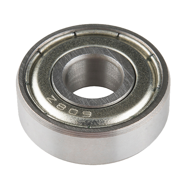 Ball Bearing - Non-Flanged (8mm Bore, 22mm OD)4 pieces
 Baltic Birch Plywood (3/4 inch, 24x30)1 sheet
 M5 Flat Washer12 pieces
 M5 Hex Nut6 pieces
Tools needed:
 Hacksaw Frame with Blades (10-Pack)
 Cordless Drill/Driver (20V)
 Drill Bit Set
 File Set
 Allen/Hex Key Set
 Digital Caliper 6-Inch
Cut a sequence of grooves, not just one
Cut a sequence of grooves, not just one
A pass schedule: each groove takes the bar one step closer to size.
- Cut matching semicircular grooves in both rolls so they form closed apertures when the rolls meet.
- Make a series: 20 mm, 16 mm, 13 mm, 10 mm and 8 mm across the roll faces.
- Align each pair of grooves exactly — a mismatch shows as a fin on the finished bar.
- Round the groove edges slightly so the bar enters without shearing.
Reduction per pass is a real constraint. Take too much in one pass and the rolls simply refuse to bite — the bar skids instead of being drawn in — and the metal cracks at its surface. Take too little and you waste passes and lose heat. Roughly 20 to 30 per cent area reduction per pass is the practical band, which is why the schedule steps down rather than jumping.
Groove alignment is the commonest fault. Offset the two halves by a millimetre and every bar carries a longitudinal fin exactly at the parting line, which must then be removed by hand — losing all the advantage the mill was built for.Tools needed:
File Set Bench ViseDigital Caliper 6-Inch
 Combination Square
 Center Punch
Add screw-down adjustment
Add screw-down adjustment
The gap must be settable, and it must hold against the separating force.
- Mount the top roll's bearings in vertical slides within the housing.
- Fit two M10 screws bearing down on those slides, one at each end.
- Fit locknuts so a setting holds.
- Set the gap with feeler gauges or shim stock at both ends and confirm they match.
Two screws, set independently, and this is why. If one end of the gap is tighter than the other, the bar is squeezed harder on one side, comes out thicker on the other, and — because the longer side must go somewhere — the bar curves as it leaves. Rolling a banana instead of a bar is nearly always an unequal gap rather than a bad groove.
Set the gap with the mill loaded if you can. Frame flex means the running gap is always larger than the static one, and the difference is exactly the error you will measure in step 4.Materials for this step:
 Aluminum Flat Bar (1x1/4 inch, 36-inch)1 pieceM5 Flat Washer8 piecesM5 Hex Nut4 pieces
Tools needed:
Cordless Drill/Driver (20V)Drill Bit SetAllen/Hex Key SetFile SetDigital Caliper 6-InchRoll a bar down the schedule and measure consistency
Roll a bar down the schedule and measure consistency
The claim is uniform section along the whole length. Test it.
- Take an annealed aluminium bar and roll it through the largest groove.
- Measure its section at five points along its length.
- Pass it through each successive groove, rotating it 90 degrees between passes.
- Measure again at five points after the final pass.
- Compare against a bar of the same reduction produced by hammering.
Materials for this step:
Aluminum Round Bar1 pieceTools needed:
Digital Caliper 6-Inch StopwatchBench Vise
Why it was patented with puddling, and history
Why it was patented with puddling, and history
Henry Cort patented grooved rolls in 1783 and the puddling process in 1784, and the two belong together. Puddling produced wrought iron as a spongy bloom full of slag; that bloom had to be worked to expel the slag and consolidate the metal, and rolling did it in minutes where hammering took hours. Neither invention is as valuable alone: puddling made the iron, rolling made it usable, and together they multiplied British wrought iron output enormously.
This is why chronological order matters for reading the catalogue. Puddling appears earlier here as a smelting process; without the rolling mill it is an interesting furnace. With it, it is the foundation of the railway age — rails, plate, angle and bar all came off grooved rolls, in sections a hammer could never hold consistently.
The deeper shift is from craft to stock. Before rolling, iron came in whatever sections a particular smith made. Afterwards it came in catalogued sections, repeatable between mills, so a structure could be designed on paper from standard parts before any metal was ordered. That is the same transition the Whitworth thread brought to fasteners and gauge blocks brought to measurement — the industrial habit of agreeing on a standard first.
Its honest limits: rolling makes long constant sections and nothing else. It cannot make a shape that varies along its length, cannot make a closed hollow without a mandrel — which is what the Mannesmann process later in this batch solves — and the tooling is a set of rolls that must be re-cut for every new section. High volume of one profile is where it wins, and that has not changed.
Materials
6- 3 piecesPlaceholder
- Ball Bearing - Non-Flanged (8mm Bore, 22mm OD)10% commission4 pieces$1.26
- 1 sheetPlaceholder
- 20 piecesPlaceholder
- 10 piecesPlaceholder
- Placeholder
Tools Required
10- Placeholder
- 1 vendor sell this, none ship to you yetPlaceholder
- Placeholder
- Placeholder
- Placeholder
- Placeholder
- Placeholder
- Placeholder
- Placeholder
- Placeholder
Related Blueprints
These blueprints share knowledge with this one — techniques, materials, or principles that connect them in the learning graph.



CC0 Public Domain
This blueprint is released under CC0. You are free to copy, modify, distribute, and use this work for any purpose, without asking permission.
Support the Maker by purchasing products through their Blueprint where they earn a Maker Commission set by Vendors, or create a new iteration of this Blueprint and include it as a connection in your own Blueprint to share revenue.