Collaboration
ART
BEAUTY & WELLNESS
CRAFT
CULTURE & HISTORY
ENTERTAINMENT
ENVIRONMENT
FOOD & DRINKS
REVERSE ENGINEERING
SCIENCES
SPORTS
TECHNOLOGY
WEARABLES
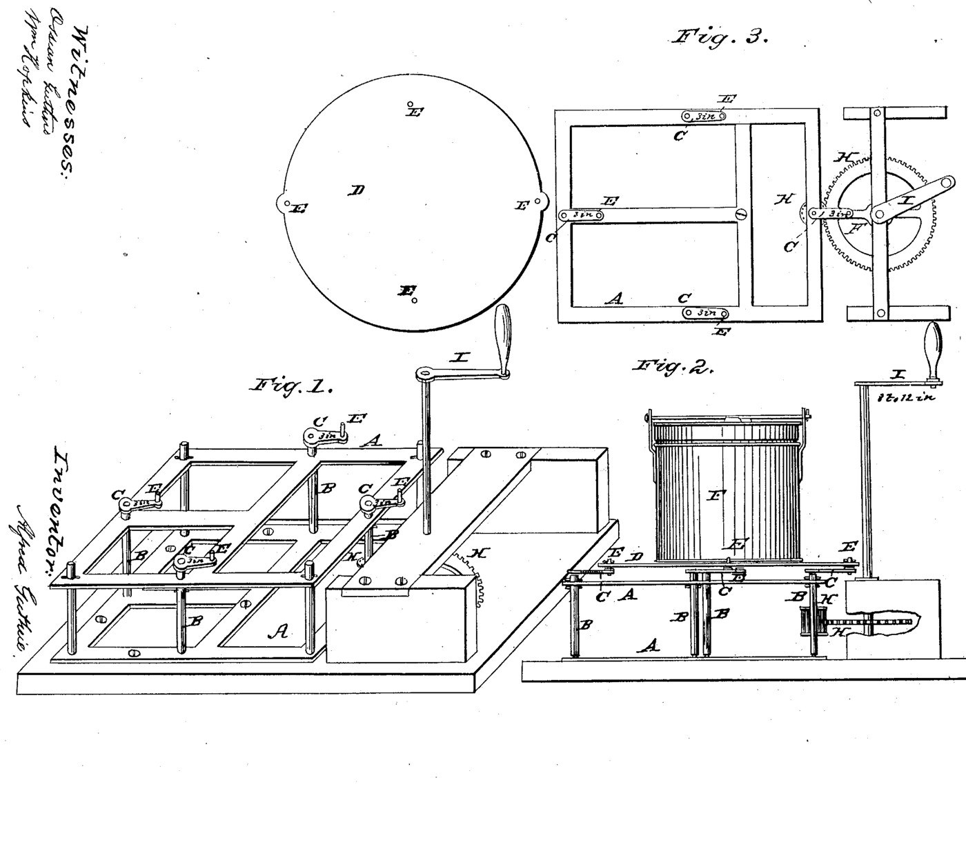


Four-Crank Gyrating Churn: Four Cranks Carry the Tub Round a Small Circle With No Dasher
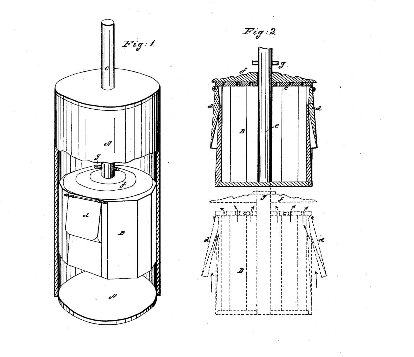
Alfred Guthrie of Chicago received US 24,907, dated 26 July 1859, for a churn with no dasher at all. Four upright shafts in a frame have cranks on their tops, and a bed plate lies over the four crank pins, so each crank turns on its own centre but all move together. The tub stands on the plate, held by stirrups, and is carried round a small circle, throwing the cream against its sides. A handle turns one crank shaft through cogged gearing.
This rung builds it at the patent's own sizes: a frame about two feet square and one foot high, shafts of 3/4 inch iron and 3 inch cranks.
Intermediate
About 2 days, plus printing
Instructions
1
1
How hard the cream is swung
How hard the cream is swung
Loading Jupyter Notebook...
2
2
A churn with a dasher, before it
A churn with a dasher, before it
Wineman's dasher drove the cream through holes. Guthrie did away with the dasher and moved the whole tub.
3
3
Read US 24,907
Read US 24,907
"I connect the whole together by the bed plate D over the wrists of each crank E, E, E, E. Each crank will revolve upon its own center but will each correspond to the motion of the other."
4
4
Print the wheel H
Print the wheel H
The 64-tooth spur wheel (module 3, 198 mm across) for the handle shaft I, with a 20 mm bore. PETG, 0.2 mm layers, 50 % infill, 5 walls.
5
5
Print the pinion H
Print the pinion H
The 24-tooth spur pinion for the driven crank shaft, with a 19 mm bore and a hub. PETG, 0.2 mm layers, 50 % infill, 5 walls.
6
6
Frame and bearing bars
Frame and bearing bars
Build a pine frame 610 mm square and 305 mm high: four 50 mm corner posts, and 50 mm rails round the top and the bottom. Fit two hardwood bars across it, top and bottom, 150 mm in front of and behind the middle, and bore them 19.6 mm square to the frame at 200 mm either side of the middle, for the four shafts. Screw two hardwood brackets to the right side, top and bottom, bored 20.6 mm 132 mm out from the front right shaft, for the handle shaft.
Materials for this step:
 Pine Board2 pieces
 Softwood Timber 70x70mm2 pieces
 Hardwood Board2 pieces
 #10 x 3" Wood Screw24 pieces
 Wood Glue1 piece
Tools needed:
 Hand Saw
 Cordless Drill
 Spade Bit Set
 Try Square
 Spirit Level
 Tape Measure
7
7
Shafts, cranks and plate D
Shafts, cranks and plate D
Cut four 19 mm steel shafts 323 mm long and stand them in the bars. Make four hardwood crank arms, 76 mm from the shaft to the crank pin, and pin them on the shafts' tops all pointing the same way. Fit a 19 mm steel crank pin 50 mm long in each. Cut plate D 532 mm across from plywood, bore it for the four pins exactly where they stand, and drop it on them. Turn one crank by hand: the plate must run round freely without turning.
Materials for this step:
 Steel Bar Stock2 piecesHardwood Board1 piece
 Plywood Sheet1 piece
 Flat Washer8 pieces
 Hex Bolt Assortment4 pieces
 Nylon Insert Lock Nut4 piecesWood Glue1 piece
Tools needed:
 Hacksaw
 Files (Hand File)
 Bench ViseCordless Drill
 Drill Bit Set
 JigsawTape Measure
 Adjustable Spanner
8
8
Gearing H and handle I
Gearing H and handle I
Pin the pinion on the front right shaft 140 mm up. Stand a 20 mm steel shaft 885 mm long in the brackets, pin the wheel on it level with the pinion, and check they mesh fully. Fix a hardwood handle arm 150 mm long on the shaft's top with a dowel grip.
Materials for this step:
 PETG Filament1 pieceSteel Bar Stock1 pieceHardwood Board1 piece
 Hardwood Dowels1 pieceWood Glue1 piece
Tools needed:
 FDM 3D PrinterHacksawCordless DrillDrill Bit Set
9
9
Tub F on its grooved bottom
Tub F on its grooved bottom
Glue a plywood ring to the plate's middle, 282 mm inside and 340 mm outside, so the bucket's foot sits in it. Bend two flat-bar stirrups to go up the bucket's sides and over its lid, notch the ring for them and bolt them to the plate.
Materials for this step:
Plywood Sheet1 pieceWood Glue1 piece Mild Steel Flat Bar2 piecesHex Bolt Assortment4 piecesNylon Insert Lock Nut4 pieces
 20-Liter Bucket1 piece
Tools needed:
JigsawBench ViseHacksawCordless DrillDrill Bit SetAdjustable Spanner10
10
The build in 3D
The build in 3D
FreeCAD model of this build: the frame with its bearing bars, the four shafts and cranks, plate D on the crank pins, the bucket in its ring under two stirrups, and the spur wheel on the handle shaft driving the pinion. It was checked at eight crank angles.
11
11
Churn
Churn
Pour about 8 litres of heavy cream at about 15 °C into the bucket, checked with the thermometer, put the lid on and tighten the stirrups. Turn the handle steadily and time it. When the butter comes, lift the bucket off, pour off the buttermilk, wash the butter in cold water until it runs clear, work in a pinch of salt and weigh it.
Materials for this step:
 Heavy Cream8 l
 Coarse Sea Salt1 piece
 Water1 piece
Tools needed:
 Leave-In Probe Thermometer
 Stopwatch
 Digital Kitchen Scale
 Stainless Steel Mixing Bowl (Large)
12
12
Troubleshooting
Troubleshooting
Four-crank churn troubleshooting.
Flow
Loading...
13
13
History and honest limits
History and honest limits
**Alfred Guthrie** of Chicago, Illinois, assignor to Wardell Guthrie, US 24,907, 26 July 1859, "Churn". He claimed the cranks C connected by the plate D. His sizes are kept: a frame about two feet square and one foot high, shafts of 3/4 inch iron about a foot long, and cranks of 3 inches, which we read from "about a six inch throw or three inches" and Fig. 3's "3 in" marks. He gives no gear sizes; ours are printed spur gears placed as his Figs. 2-3 draw them. Every other size is ours.
Materials
17- 2 piecesPlaceholder
- 2 piecesPlaceholder
- 2 piecesPlaceholder
- 24 piecesPlaceholder
- 4 piecesPlaceholder
- 2 piecesPlaceholder
- 1 piecePlaceholder
- 8 piecesPlaceholder
- 8 piecesPlaceholder
- 8 piecesPlaceholder
- 1 piecePlaceholder
- 1 piecePlaceholder
- 2 piecesPlaceholder
- 1 piecePlaceholder
- 8 lPlaceholder
- 1 piecePlaceholder
- 1 piecePlaceholder
Tools Required
17- Placeholder
- 1 vendor sell this, none ship to you yetPlaceholder
- Placeholder
- Placeholder
- Placeholder
- 1 vendor sell this, none ship to you yetPlaceholder
- Placeholder
- Placeholder
- Placeholder
- Placeholder
- 1 vendor sell this, none ship to you yetPlaceholder
- Placeholder
- Placeholder
- Placeholder
- Placeholder
- Placeholder
- Placeholder
Design Files
3This blueprint makes


Related Blueprints
These blueprints share knowledge with this one — techniques, materials, or principles that connect them in the learning graph.



CC0 Public Domain
This blueprint is released under CC0. You are free to copy, modify, distribute, and use this work for any purpose, without asking permission.
Support the Maker by purchasing products through their Blueprint where they earn a Maker Commission set by Vendors, or create a new iteration of this Blueprint and include it as a connection in your own Blueprint to share revenue.