ART
BEAUTY & WELLNESS
CRAFT
CULTURE & HISTORY
ENTERTAINMENT
ENVIRONMENT
FOOD & DRINKS
REVERSE ENGINEERING
SCIENCES
SPORTS
TECHNOLOGY
WEARABLES
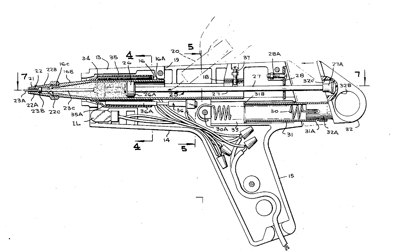


Hot Glue Gun: Weller & Brassaw, 1973
Carl E. Weller and Alden J. Brassaw, for Cooper Industries, patented this glue gun in 1973, US 3,744,921. A stick of solid hot-melt adhesive drops through a loading well into a tubular melt chamber that narrows to a nozzle. Mica sheet wound with nichrome wire and closed by a metal sleeve heats the chamber, under a thermostat. Instead of a thumb, ratchet or feed wheel pushing the stick, a spring drives a Teflon-tipped piston forward against it. A valve pin in the nozzle keeps it closed against dripping; pressing the projecting pin on the work opens it and the glue flows.
Advanced
Factory process
Instructions
1
1
Housing and melt chamber
Housing and melt chamber
Fit the elongated tubular melt chamber between the two pistol-shaped housing halves: a uniform cylindrical barrel with a loading well opening through the top of the housing, a converging conical forward part and a threaded end.
Materials for this step:
 Glue Gun Housing Halves1 piece
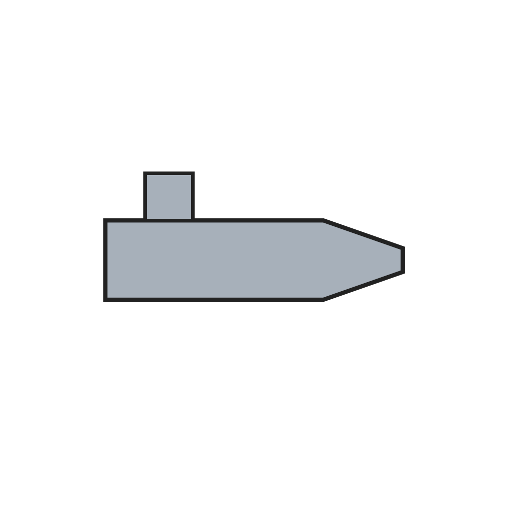 Tubular Melt Chamber1 piece
Tools needed:
 Screwdriver Set
2
2
Heater
Heater
Wrap mica sheeting spirally round the barrel with nichrome windings between the layers, close it in a tubular metal sleeve, and fit the thermostat in its well against it.
Materials for this step:
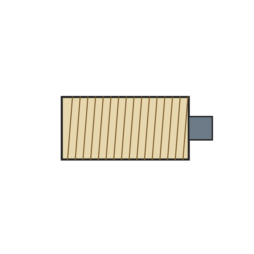 Mica-Wound Nichrome Heater with Thermostat1 piece
 Nichrome Wire1 as required
 Mica Sheet1 as required
Tools needed:
 Combination Pliers
3
3
Nozzle and valve
Nozzle and valve
Screw the nozzle onto the threaded end. Inside it, the valve pin's enlarged portion seats against the bore's step and its tip projects from the outlet; glue pressure holds it shut until the tip is pressed against the work.
Materials for this step:
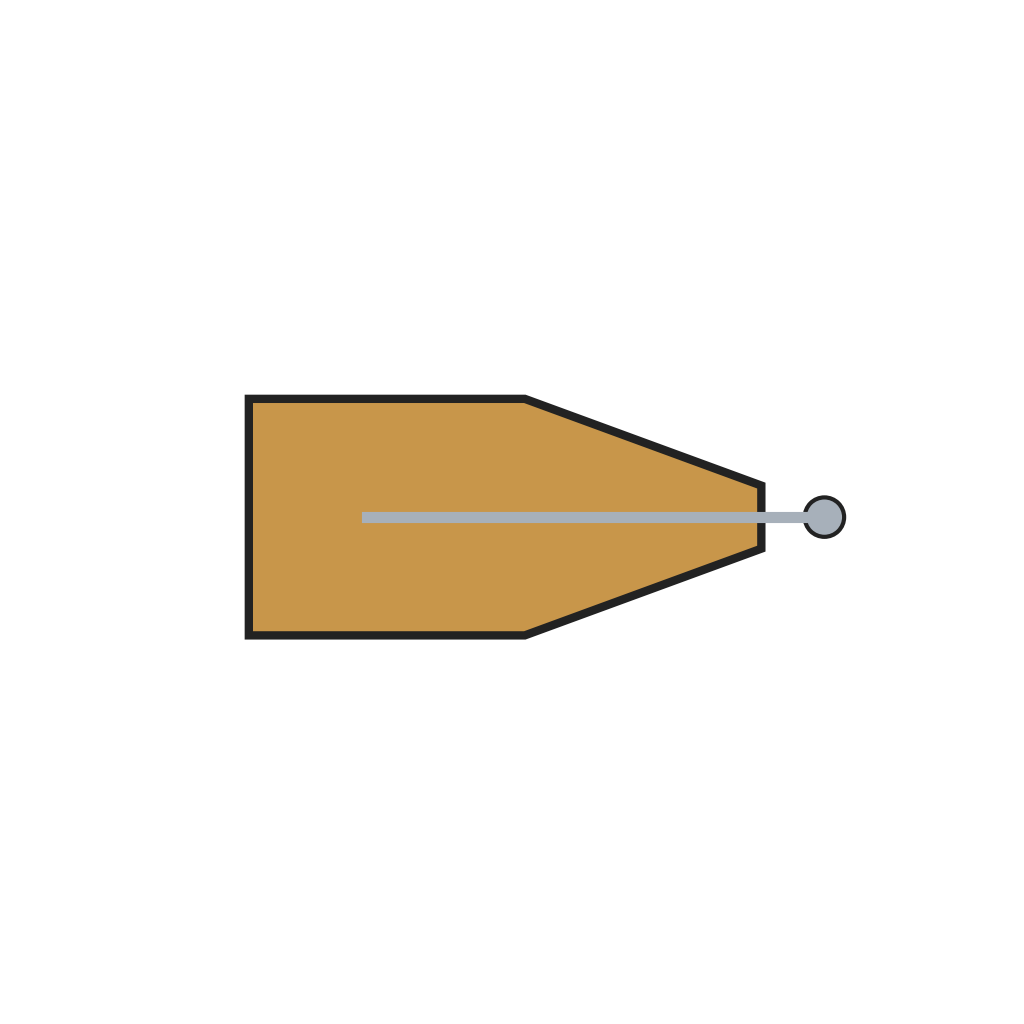 Valved Glue Nozzle1 piece
Tools needed:
 Adjustable Wrench
4
4
Plunger
Plunger
Fit the plunger, a Teflon piston on a rod guided by a plate, behind the loading well, with its knob outside the housing; couple it to the spring in its tube through the pull device so the spring pushes the glue stick forward.
Materials for this step:
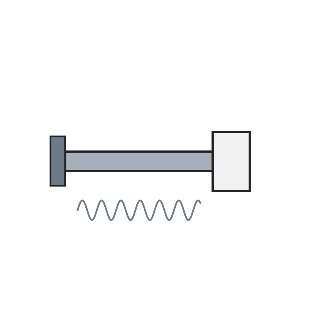 Spring-Loaded Plunger with Teflon Piston1 piece
Tools needed:
Screwdriver SetMaterials
7- 1 piecePlaceholder
- 1 piecePlaceholder
- Placeholder
- 1 as requiredPlaceholder
- 1 as requiredPlaceholder
- 1 piecePlaceholder
- Placeholder
Tools Required
3- Placeholder
- Placeholder
- Placeholder
This blueprint makes
Related Blueprints
These blueprints share knowledge with this one — techniques, materials, or principles that connect them in the learning graph.
CC0 Public Domain
This blueprint is released under CC0. You are free to copy, modify, distribute, and use this work for any purpose, without asking permission.
Support the Maker by purchasing products through their Blueprint where they earn a Maker Commission set by Vendors, or create a new iteration of this Blueprint and include it as a connection in your own Blueprint to share revenue.