ART
BEAUTY & WELLNESS
CRAFT
CULTURE & HISTORY
ENTERTAINMENT
ENVIRONMENT
FOOD & DRINKS
REVERSE ENGINEERING
SCIENCES
SPORTS
TECHNOLOGY
WEARABLES
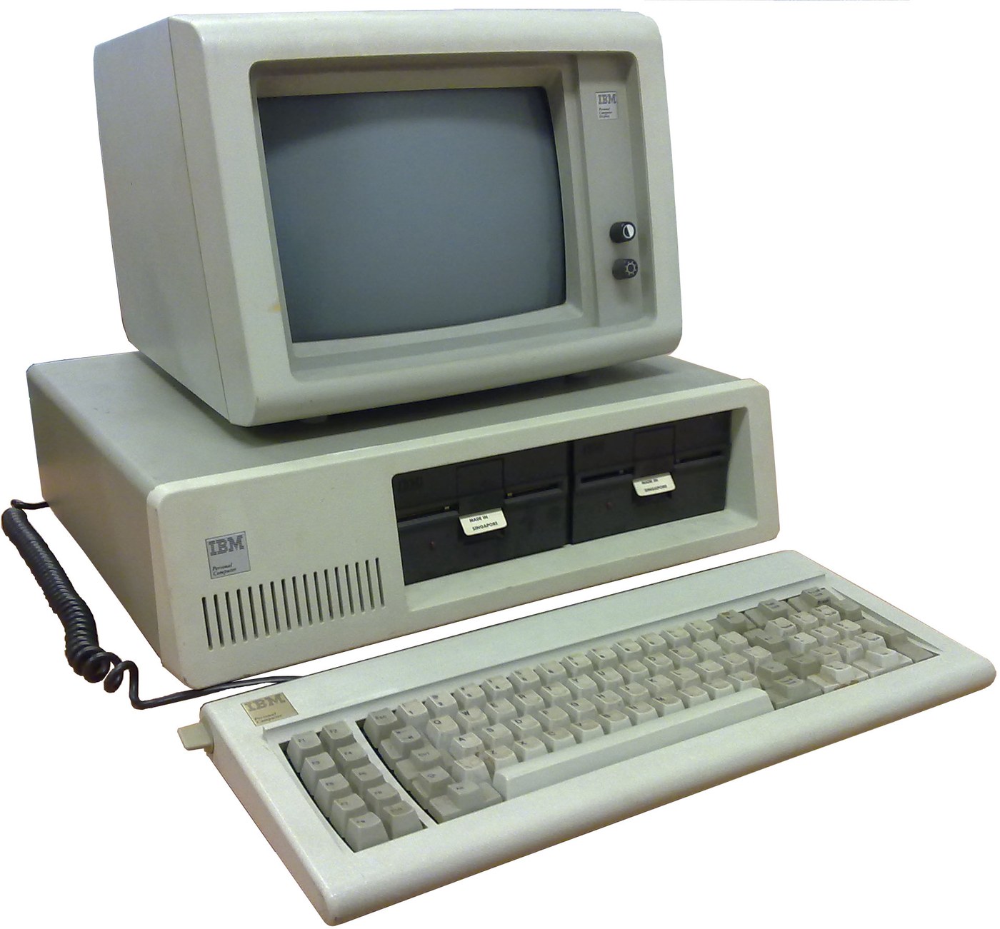


IBM Personal Computer (5150): System Unit, Keyboard and Display (IBM Technical Reference, 1981)
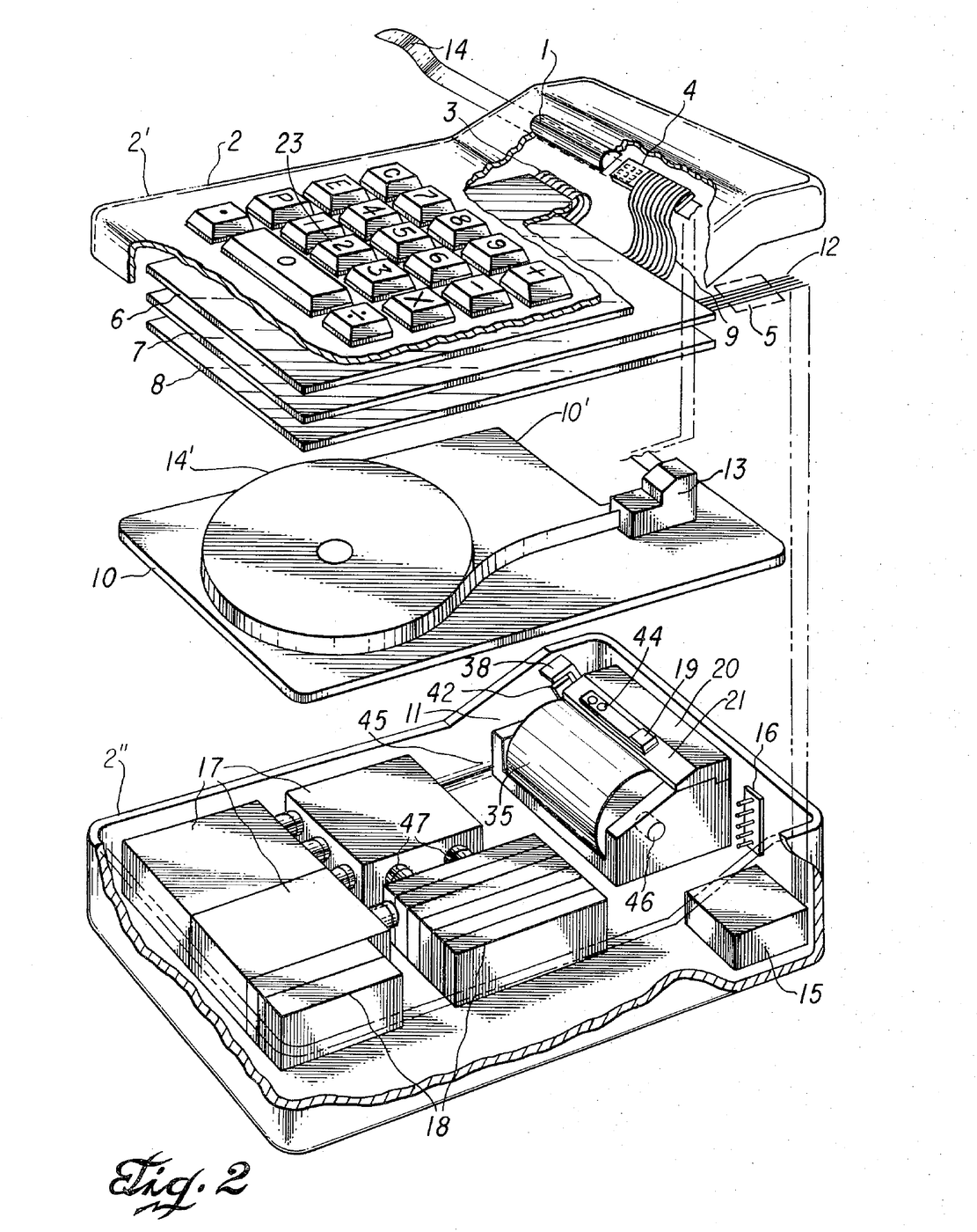
IBM's first personal computer, the machine today's desktop PCs descend from. One system unit holds an Intel 8088 system board, a power supply and five expansion slots. A keyboard, a display and 5-1/4 inch diskette drives complete it. IBM published its whole design, down to the BIOS program, in the Technical Reference.
Result: an IBM PC that tests itself at power-on and starts an operating system from diskette.
Source: IBM Personal Computer Technical Reference (1981; edition of April 1984). Unknown: the chassis and its sizes, the display and diskette adapter cards (described in IBM's separate Options and Adapters volumes), and how each part is made. Ours: the assembly order. Picture: Wikimedia Commons.
Advanced
1 week
Instructions
1
1
Populate the system board
Populate the system board
On the system board, fit the Intel 8088 processor. It runs at 4.77 MHz, taken from a 14.31818 MHz crystal divided by 3; divided by 4, the same crystal gives the 3.58 MHz colour-burst signal for colour TVs. Fit its support chips: the 8237A-5 DMA controller, 8259A interrupt controller, 8253-5 timer and 8255A-5 peripheral interface. Add the ROM holding the BIOS, the read/write memory, the speaker circuit, five expansion slots, and 5-pin DIN sockets for the keyboard and a cassette recorder. The 8088 runs in maximum mode, so a coprocessor can be added later. Set switch SW1 to tell the machine what it has: whether to start from a 5-1/4 inch diskette drive, how much read/write memory is on the board, which display adapter is fitted, and how many diskette drives there are. Not given here: the board layout.
Materials for this step:
 Printed Circuit Board1 system board
 Integrated Circuit1 8088, 8237A-5, 8259A, 8253-5, 8255A-5, ROM, RAM
 Quartz Crystal1 14.31818 MHz
 IBM PC BIOS1 in ROM
 DIP Switch1 SW1
 Solder Wire1 as needed
Tools needed:
 Soldering Iron
2
2
Fit the board and power supply in the chassis
Fit the board and power supply in the chassis
Screw the system board into the system-unit chassis. Fit the power supply at the right rear; its housing supports the rear panel and its fan cools the whole machine. It is rated for 63.5 W continuous, from a fused 120 V or 220/240 V input. Its four protected outputs are +5 V at 7 A, +12 V at 2 A, -5 V at 0.3 A and -12 V at 0.25 A, bussed to all five slots. It also has a power-good signal, a switched mains socket for the monochrome display and two drive power plugs. Not given: the chassis metal and sizes.
Materials for this step:
 Unknown Metal1 chassis
 Computer Power Supply1 63.5 W
 Machine Screws1 set
Tools needed:
 Screwdriver Set
 Unknown Dimensions
 Multimeter
3
3
Add the drives and adapter cards
Add the drives and adapter cards
Fit up to two 5-1/4 inch diskette drives, each powered from its own plug on the supply. Only one drive runs at a time. Plug a diskette drive adapter and a display adapter (monochrome or colour/graphics) into expansion slots, and cable the drives to their adapter. Not given here: the adapter cards and cables, which IBM describes in its separate Options and Adapters volumes.
Materials for this step:
 5-1/4 Inch Diskette Drive2 up to two
 Expansion Card2 diskette adapter, display adapter
 Ribbon Cable1 drive cable
Tools needed:
Screwdriver Set4
4
Connect keyboard and display, and power on
Connect keyboard and display, and power on
Plug in the keyboard: 83 keys, with the typewriter keys in the middle, 10 function keys on the left and a 15-key pad on the right. It sends scan codes, not letters, so the software decides what each key does. Connect the display to its adapter and to the switched socket. Switch on: the power-on self-test in the BIOS checks the machine, sets up its interrupt vectors, and looks for extra ROM on the adapter cards. The bootstrap loader then starts the operating system from a diskette.
Materials for this step:
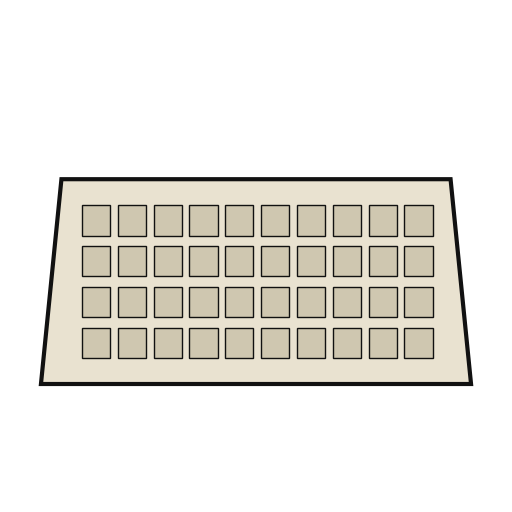 Computer Keyboard1 83 keys
 Computer Monitor1 piece
Tools needed:
 Floppy Disk
Materials
14- 1 system boardPlaceholder
- 1 8088, 8237A-5, 8259A, 8253-5, 8255A-5, ROM, RAMPlaceholder
- 1 14.31818 MHzPlaceholder
- 1 in ROMPlaceholder
- Placeholder
- 1 as neededPlaceholder
- 1 chassisPlaceholder
- 1 63.5 WPlaceholder
- 1 setPlaceholder
- 2 up to twoPlaceholder
- 2 diskette adapter, display adapterPlaceholder
- Placeholder
- 1 83 keysPlaceholder
- 1 piecePlaceholder
Tools Required
5- 2 vendors sell this, none ship to you yetPlaceholder
- Placeholder
- Placeholder
- Placeholder
- Placeholder
Connected Blueprint Materials
This blueprint makes
CC0 Public Domain
This blueprint is released under CC0. You are free to copy, modify, distribute, and use this work for any purpose, without asking permission.
Support the Maker by purchasing products through their Blueprint where they earn a Maker Commission set by Vendors, or create a new iteration of this Blueprint and include it as a connection in your own Blueprint to share revenue.