ART
BEAUTY & WELLNESS
CRAFT
CULTURE & HISTORY
ENTERTAINMENT
ENVIRONMENT
FOOD & DRINKS
REVERSE ENGINEERING
SCIENCES
SPORTS
TECHNOLOGY
WEARABLES
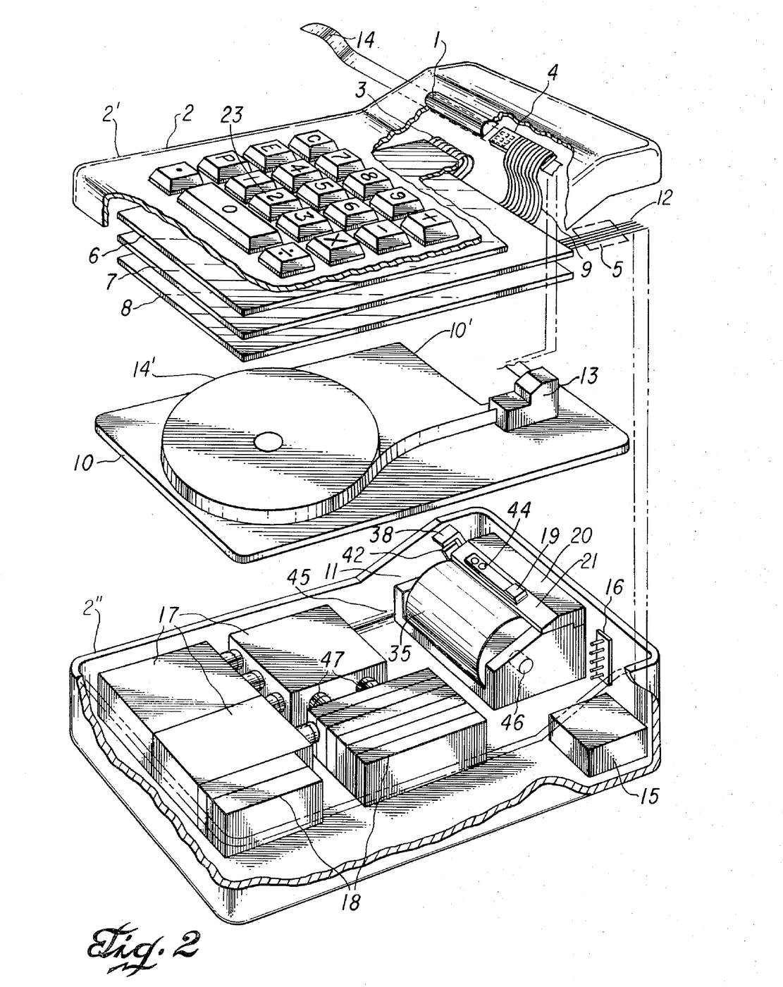


Miniature Printing Electronic Calculator: Kilby, Merryman & Van Tassel, 1974
Jack S. Kilby, Jerry D. Merryman and James H. Van Tassel of Texas Instruments first filed for this portable calculator in 1967; the patent, US 3,819,921, was granted in 1974. It adds, subtracts, multiplies and divides. All the arithmetic and control is done by one integrated semiconductor circuit array lying flat under the keyboard encoder. Answers are printed by a thermal print head, a 3 × 5 array of heater elements on a semiconductor wafer, on heat-sensitive paper tape read through a magnifying window. The case measured 4¼ × 6⅛ × 1¾ inches and the calculator weighed 45 ounces, running on batteries.
Advanced
Factory process
Instructions
1
1
Keys and encoder
Keys and encoder
Mount the 18 keys (0–9, +, −, ×, ÷, the decimal point, C for clear, E for error and P for print) in stepped holes in the upper case. Each key shaft slides in a bearing; a helix spring under the shaft head returns it, guide pins stop it turning, and a resilient pad at its base carries a thin gold-plated copper strip. Below lies the encoder: conductive strips on an insulating board, grouped so each key shorts its own set of output terminals and encodes its digit in excess-3 binary code.
Materials for this step:
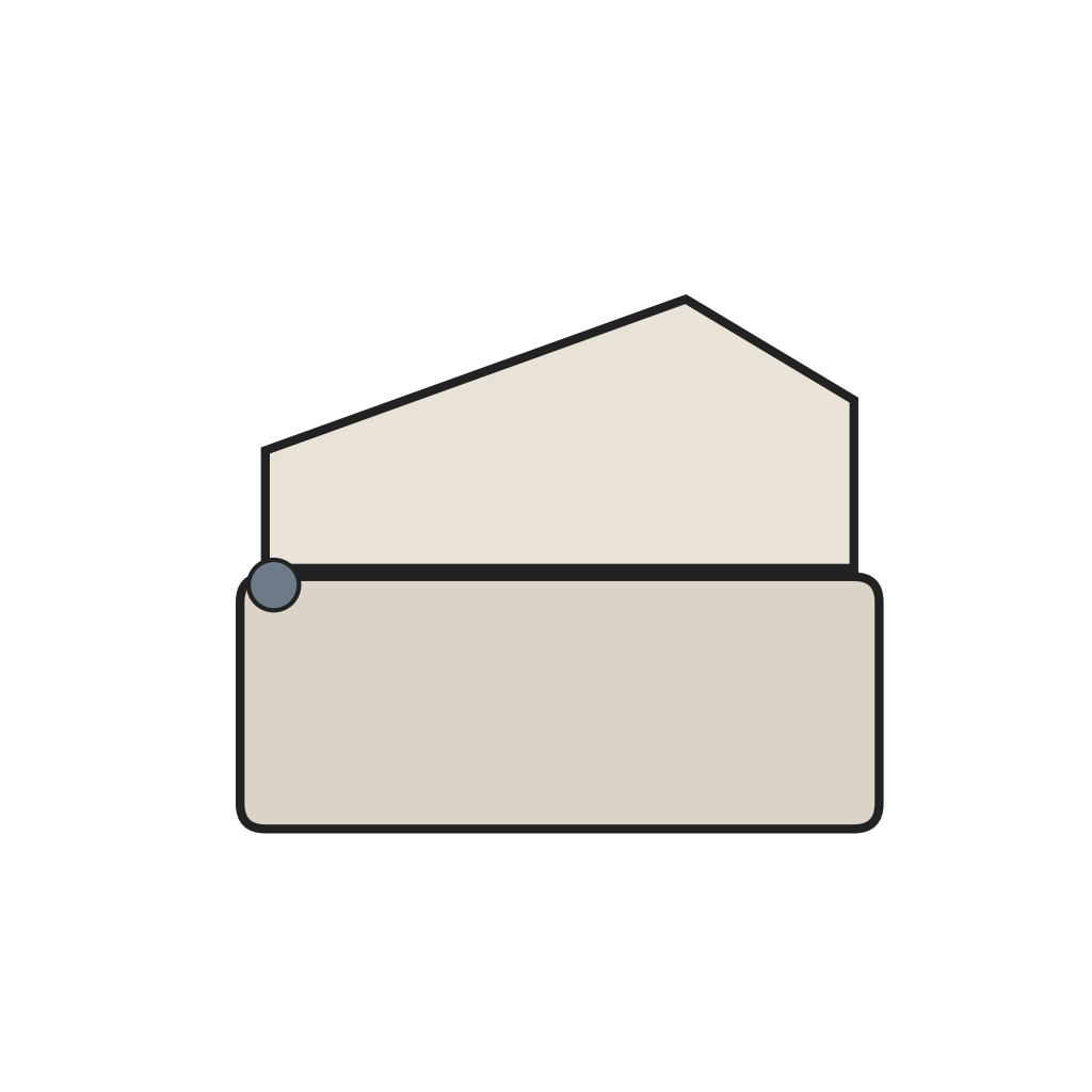 Hinged Two-Part Calculator Casing1 piece
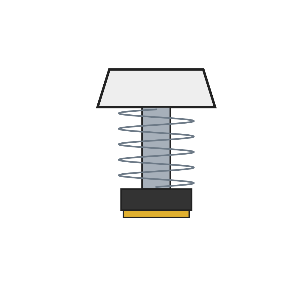 Spring-Return Key with Contact Pad18 pieces
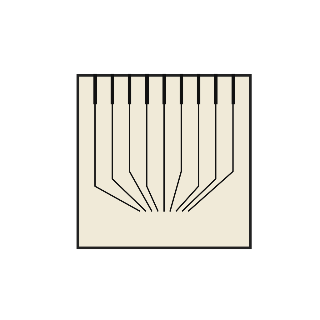 Keyboard Encoder Board1 piece
2
2
Primary electronics
Primary electronics
Mount the integrated circuit array below the encoder, in a plane parallel to it, and connect the encoder's terminals to it. The array holds the arithmetic and control sections, generating the timing signals for calculating, printing and advancing the tape.
Materials for this step:
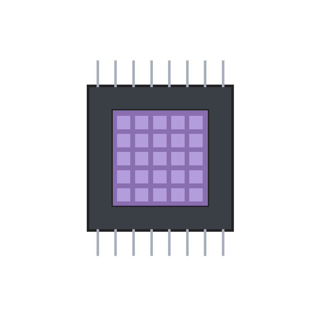 Integrated Circuit Calculator Array1 piece
3
3
Printer and tape
Printer and tape
Place the thermal print head above a resilient pressure pad, its wafer surface against the tape. Rest the tape reel on a shelf; the tape runs up through a guide block, over the pad under the print head, past the magnifying lens window and out through the side of the case. A solenoid tape-advance mechanism steps the tape on after each line: its coil pulls a pivoted clapper, a spring-biased clutch grips the tape against a clutch plate, and a drive spring pushes it forward when the coil releases. An insulating acrylic cover plate separates the shelf from the primary electronics.
Materials for this step:
 Integrated Semiconductor Thermal Print Head1 piece
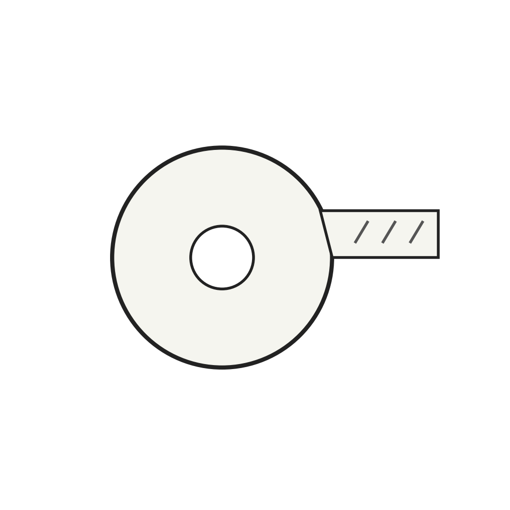 Heat-Sensitive Paper Tape1 piece
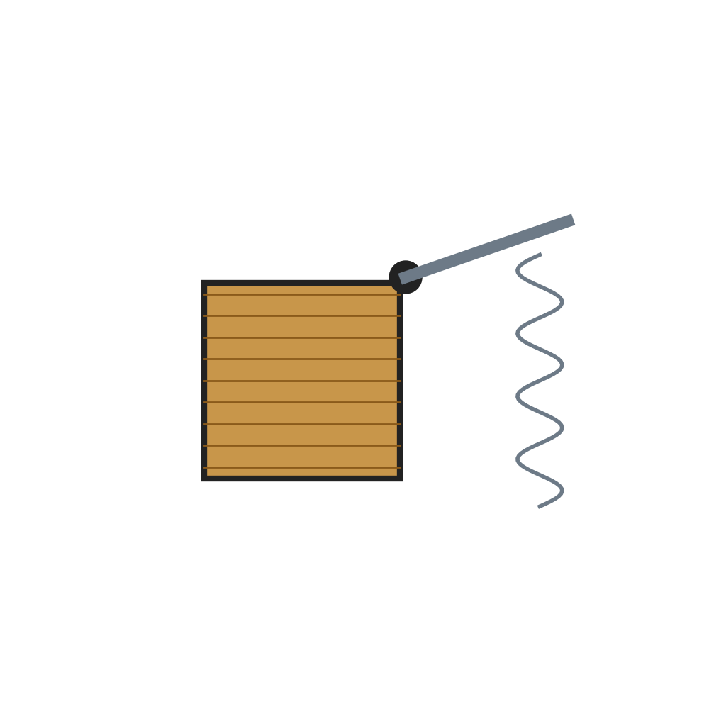 Solenoid Tape Advance Mechanism1 piece
 Magnifying Lens Window1 piece
 Acrylic Sheet1 piece
4
4
Power
Power
Fix the batteries, the auxiliary electronics module and the tape advance on the floor of the lower case. Three 1½ volt cells in series give 4½ volts and eight in series give 12 volts; the auxiliary module drives the tape-advance coil and the print timing. Wire the supply through the on/off switch to the primary electronics, and fit a battery charger plug in the wall of the lower case. Hinge and latch the two case halves so the top lifts for access.
Materials for this step:
 1.5 V Cell11 pieces
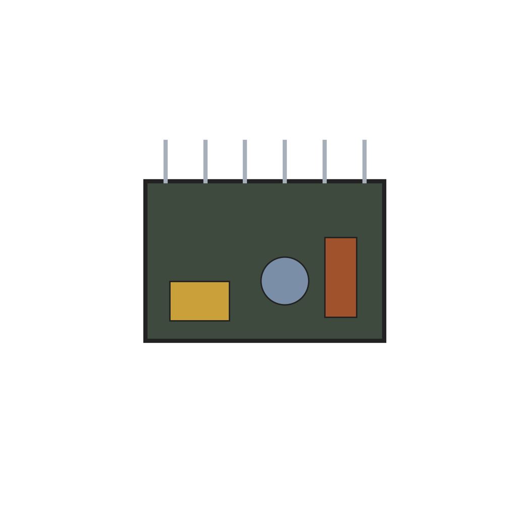 Auxiliary Electronics Module1 piece
 On/Off Switch1 piece
Materials
12- Placeholder
- 18 piecesPlaceholder
- 1 piecePlaceholder
- Placeholder
- Placeholder
- 1 piecePlaceholder
- Placeholder
- 1 piecePlaceholder
- 1 piecePlaceholder
- 11 piecesPlaceholder
- 1 piecePlaceholder
- 1 piecePlaceholder
This blueprint makes

Related Blueprints
These blueprints share knowledge with this one — techniques, materials, or principles that connect them in the learning graph.

CC0 Public Domain
This blueprint is released under CC0. You are free to copy, modify, distribute, and use this work for any purpose, without asking permission.
Support the Maker by purchasing products through their Blueprint where they earn a Maker Commission set by Vendors, or create a new iteration of this Blueprint and include it as a connection in your own Blueprint to share revenue.