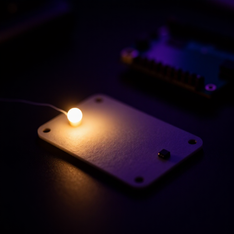


Making a LilyPad Night-Light
Give your fabric a sense of sight. A LilyPad light sensor tells the microcontroller how bright the room is, and a short program switches an LED on when it gets dark. Sew it into a bag, a hat or a bedside patch for a soft glow that only appears at night — your first sensor-driven wearable.
Instructions
Sew the board, sensor and LED
Sew the board, sensor and LED
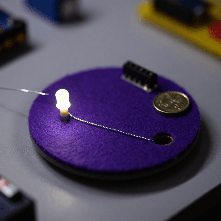
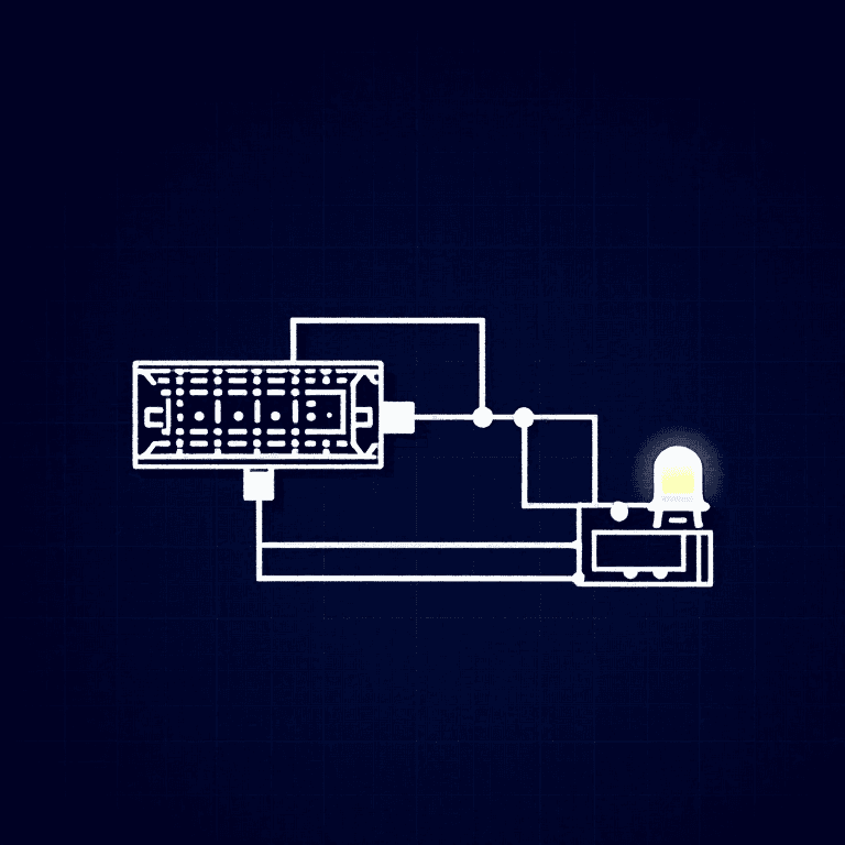
Sew a LilyPad Arduino, a LilyPad light sensor and a LilyPad LED onto felt. Wire it: the LED's + tab to pin 5 and its - tab to -; the sensor's + tab to the board's +, its - tab to -, and its signal (S) tab to analog pin A2. Keep the power (+), ground (-) and signal lines from crossing anywhere.
Materials for this step:
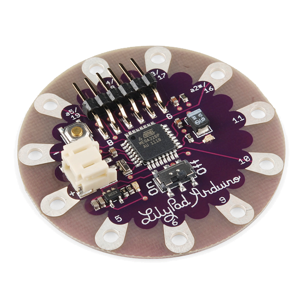 LilyPad Arduino Simple Board1 piece
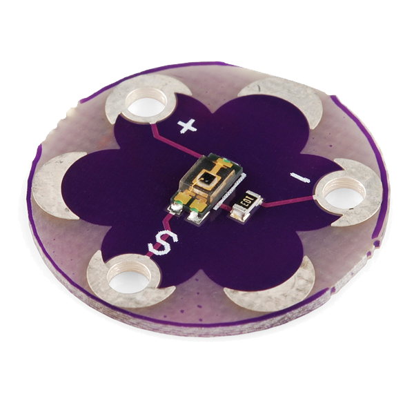 LilyPad Light Sensor1 piece
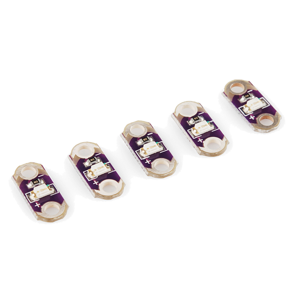 LilyPad LED - 5 pcs1 pack
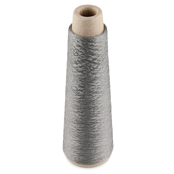 Conductive Thread - 60g (Stainless Steel)1 spool
 Wool Felt Sheet1 sheet
Tools needed:
 Hand Sewing Needles (Assorted, 30-Pack)
Connect the programmer
Connect the programmer
Plug the LilyPad FTDI onto the programming header and connect the USB cable to your computer. Open the Arduino IDE and select the LilyPad Arduino board and its serial port.
Tools needed:
 Computer with Arduino IDE
 LilyPad FTDI Basic Breakout - 5V
 USB-B Cable
Upload the night-light sketch
Upload the night-light sketch
Paste this sketch and click Upload. It reads the light sensor and turns the LED on whenever the room is darker than the threshold.
Calibrate the threshold
Calibrate the threshold
Cover the sensor with your hand — the LED should come on; in a bright room it should stay off. If it triggers too early or too late, change the threshold number in the sketch and re-upload: higher turns it on in more light, lower waits for darker.
Go wireless and wear it
Go wireless and wear it
Unplug the FTDI, sew a LilyPad coin-cell holder to the board (+ to +, - to -), drop in a CR2032 and switch on. Sew the felt onto a bag, hat or cushion — it now glows on its own whenever the light drops.
Materials for this step:
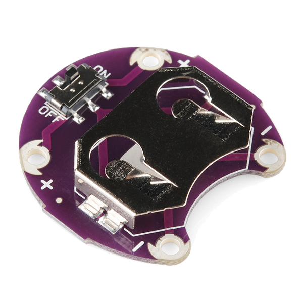 LilyPad Coin Cell Battery Holder - w/Switch - 20mm1 piece
 CR2032 Coin Cell Battery1 piece
Materials
7- LilyPad Arduino Simple Board10% commission1 piece$19.60
- LilyPad Light Sensor10% commission1 piece$7.62
- LilyPad LED - 5 pcs10% commission1 pack$4.20
- Conductive Thread - 60g (Stainless Steel)10% commission1 spool$40.13
- 1 sheetPlaceholder
- LilyPad Coin Cell Battery Holder - w/Switch - 20mm10% commission1 piece$5.05
- 1 piecePlaceholder
Tools Required
4- Placeholder
- Placeholder
- LilyPad FTDI Basic Breakout - 5V10% commission$14.38
- 1 vendor sell this, none ship to you yetPlaceholder
Related Blueprints
These blueprints share knowledge with this one — techniques, materials, or principles that connect them in the learning graph.
CC0 Public Domain
This blueprint is released under CC0. You are free to copy, modify, distribute, and use this work for any purpose, without asking permission.
Support the Maker by purchasing products through their Blueprint where they earn a Maker Commission set by Vendors, or create a new iteration of this Blueprint and include it as a connection in your own Blueprint to share revenue.