ART
BEAUTY & WELLNESS
CRAFT
CULTURE & HISTORY
ENTERTAINMENT
ENVIRONMENT
FOOD & DRINKS
REVERSE ENGINEERING
SCIENCES
SPORTS
TECHNOLOGY
WEARABLES
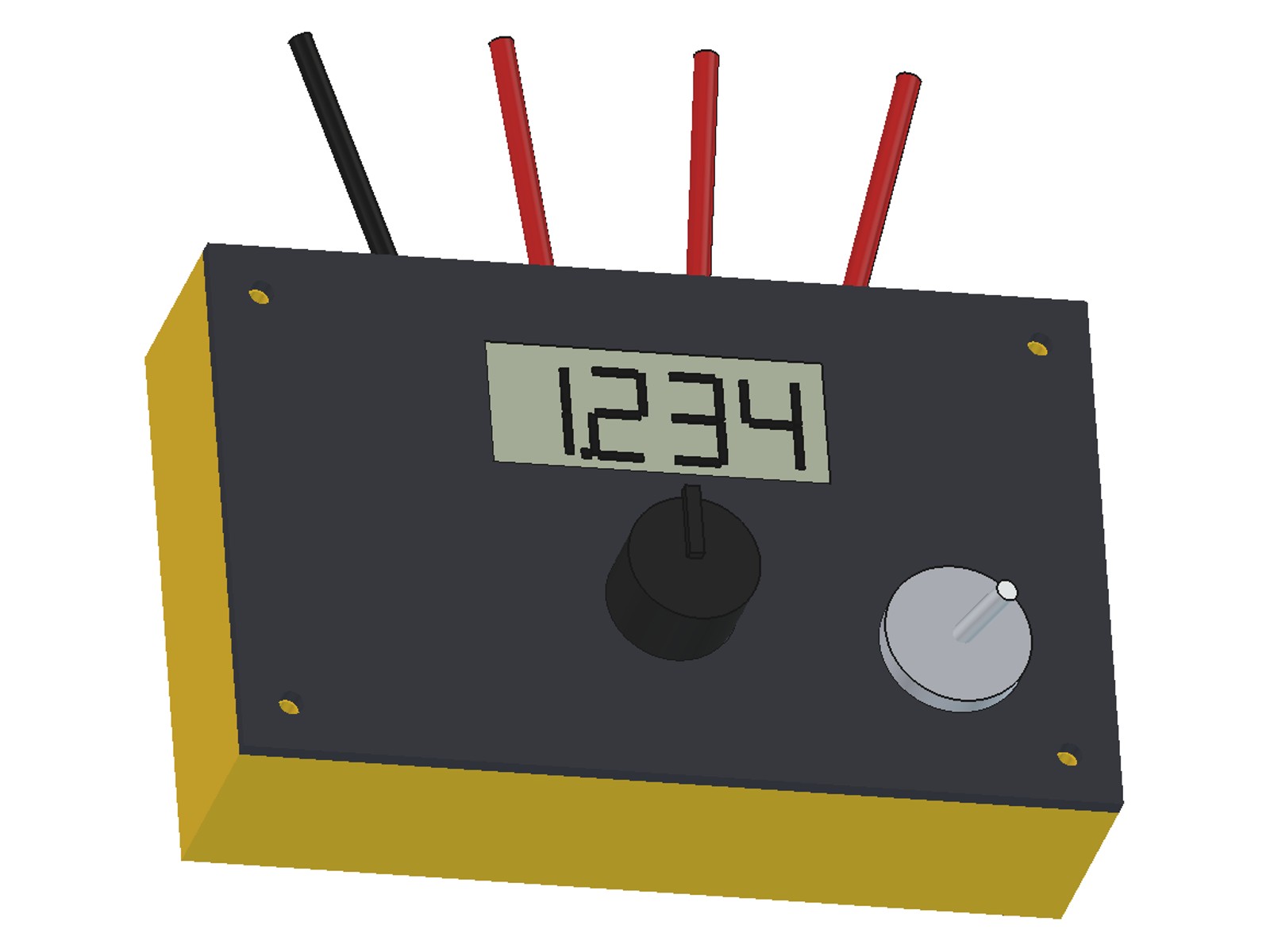


Multimeter: a Low-Voltage Pocket Meter on the ICL7106 Dual-Slope Converter (after Ammann, 1967)
A 3 1/2-digit digital multimeter for low-voltage projects: 2 V and 20 V DC, 200 mA and 2 kohm. One ICL7106 chip does the measuring by the dual-slope method Stephan Ammann patented in 1967: it integrates the input for a fixed time, then times how long a reference takes to bring it back to zero. Built on perfboard in a printed case. Never for mains.
Intermediate
About 1 day
Instructions
1
1
The dual-slope method
The dual-slope method
US 3,316,547 (Ammann, Fairchild, 1967): integrate the input over a fixed time, then integrate a reference of opposite sign until the integrator is back where it started. The time that takes, counted in clock pulses, is the ratio of input to reference, so the clock and the capacitor's exact values cancel out. The ICL7106 does this on one chip and drives the LCD directly.
2
2
Clock, ranges and the ohms circuit
Clock, ranges and the ohms circuit
Loading Jupyter Notebook...
3
3
Print the wiring sheet
Print the wiring sheet
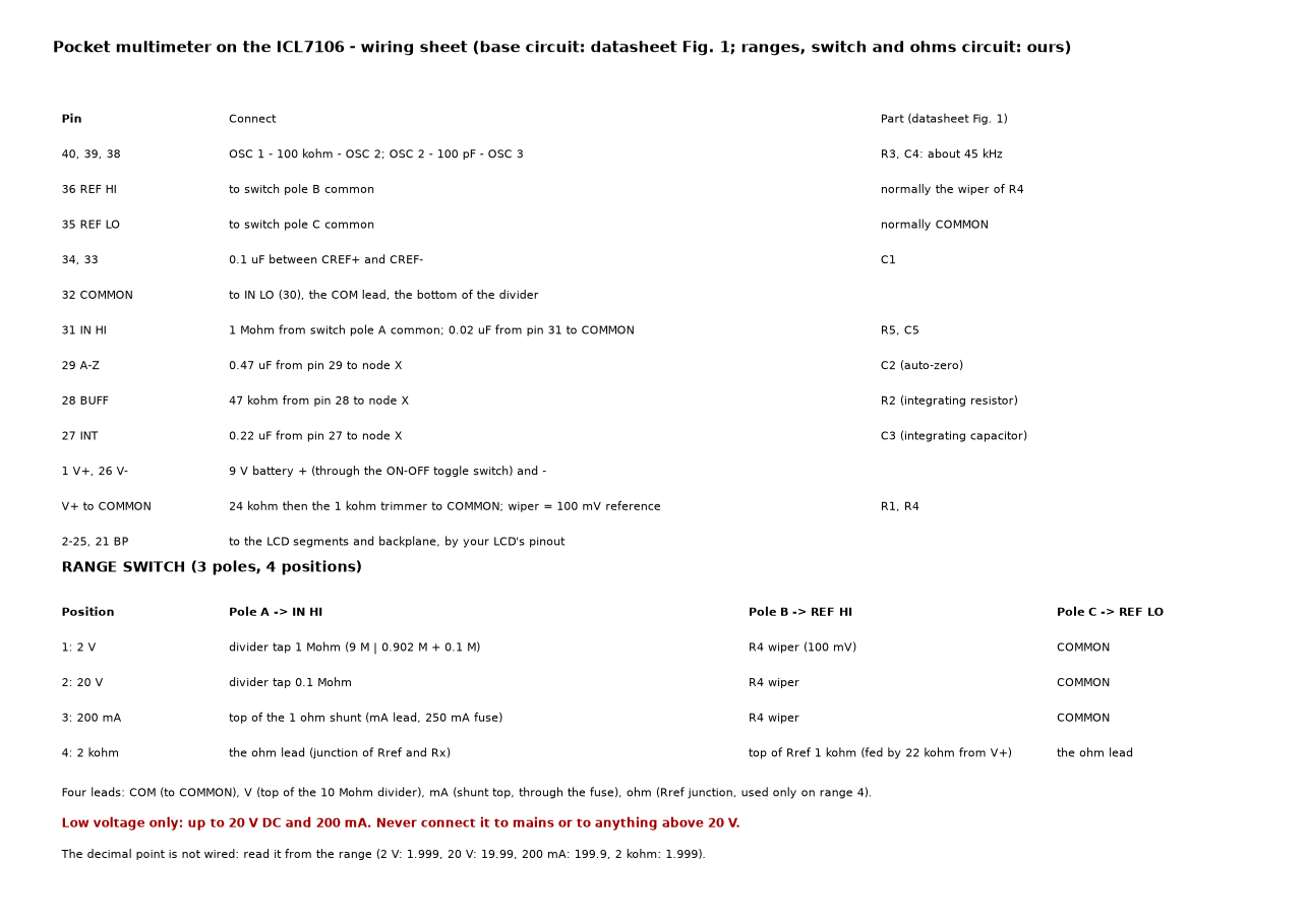
Pin by pin, the base circuit (datasheet Fig. 1 values) and the range switch table.
4
4
Print the case
Print the case
Floor down, no supports, PETG. Four holes in the top end for the leads.
Materials for this step:
 PETG Filament60 g
Tools needed:
 FDM 3D Printer
5
5
Print the lid
Print the lid
Flat, no supports. Trim the LCD window to your display; the two round holes take the range switch and the toggle switch.
Materials for this step:
PETG Filament30 gTools needed:
FDM 3D Printer6
6
Change the case (optional)
Change the case (optional)
The FreeCAD script that made the case: OUT=. freecadcmd build_all.py
build_all.pypython
Tools needed:
 Digital Caliper 6-Inch
7
7
Build the converter
Build the converter
On perfboard, wire the ICL7106 as the sheet's first table: oscillator 100 kohm and 100 pF; reference 24 kohm and the 1 kohm trimmer; 0.1 uF reference capacitor; 47 kohm, 0.47 uF and 0.22 uF (polypropylene) to node X; 1 Mohm and 0.02 uF at IN HI. Connect the LCD segments and backplane by your LCD's pinout.
Materials for this step:
 Integrated Circuit1 piece (ICL7106, 40-pin DIP)
 Segment LCD Panel1 piece (3 1/2-digit, static drive)
 Perfboard / Protoboard1 piece
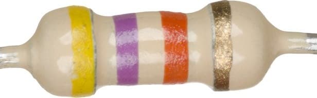
 Precision Resistor Kit8 piece (1 %: 24k, 47k, 100k, 1M, 22k, 1k and the divider below)
 Capacitor Kit5 piece (0.1, 0.47, 0.22 polypropylene, 0.02 uF, 100 pF)
 Potentiometer1 piece (1 kohm trimmer)
 Solder Wire5 g
Tools needed:
 Soldering Iron
8
8
Wire the ranges
Wire the ranges
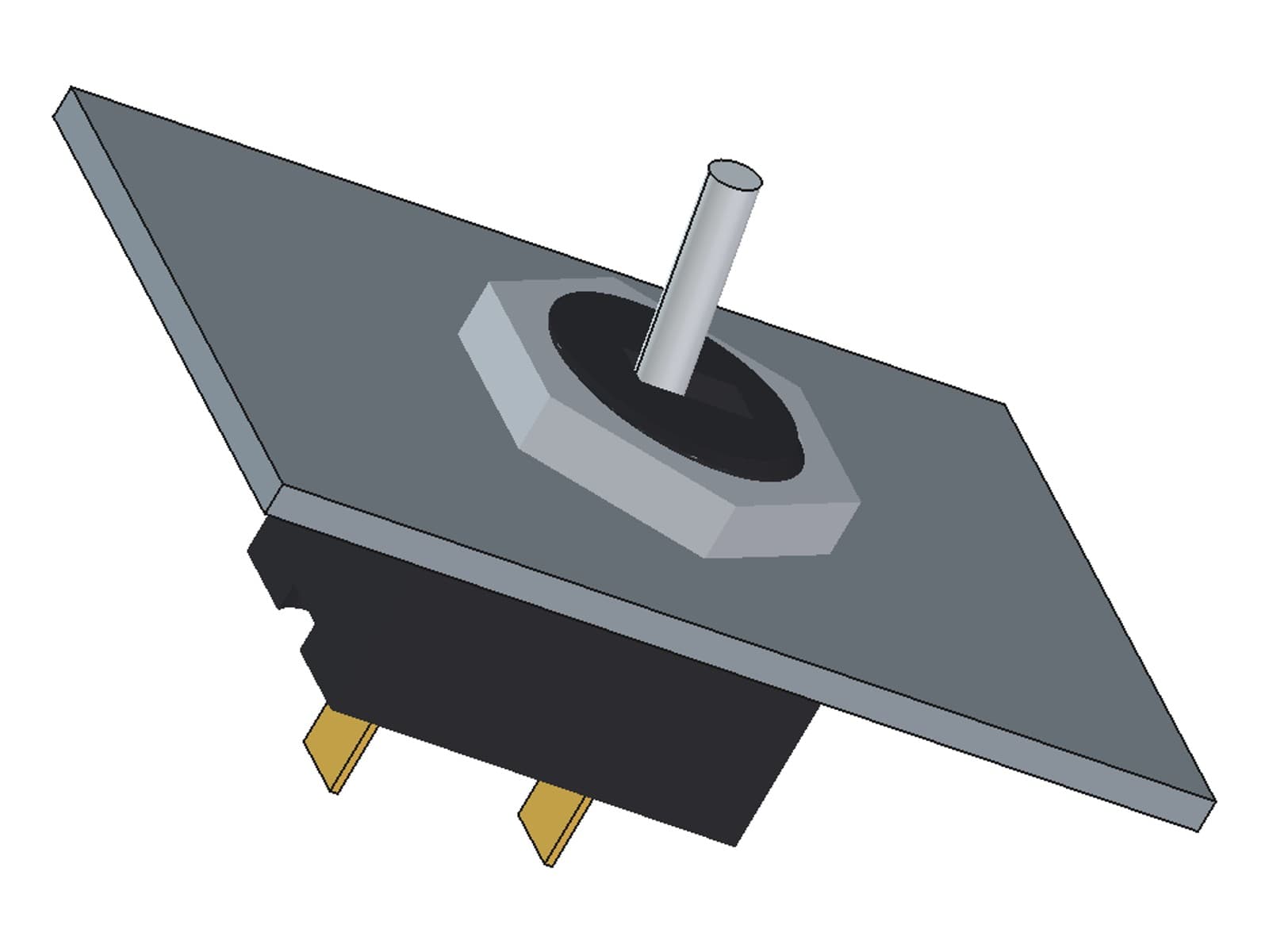
Divider from the V lead to COMMON: 4.7 M + 4.3 M, then 820 k + 82 k, then 100 k (2 V tap between the 4.3 M and the 820 k; 20 V tap between the 82 k and the 100 k). Shunt: mA lead, 250 mA fuse, 1 ohm 1 % to COMMON. Ohms: V+, 22 kohm, 1 kohm Rref, ohm lead. Wire the 3-pole 4-position switch as the sheet's second table; power through the toggle switch.
Materials for this step:
Precision Resistor Kit6 piece (1 %: 4.7M, 4.3M, 820k, 82k, 100k) Resistor Kit1 piece (1 ohm, 0.5 W)
 Rotary Switch1 piece (3 pole, 4 position)
 Toggle Switch1 piece
 Fuse1 piece (250 mA)
 DC Fuse Holder1 piece
 Battery1 piece (9 V)
 Hookup Wire1 m
Tools needed:
Soldering Iron Wire Strippers
9
9
Fit it in the case
Fit it in the case
Put the four leads (COM black; V, mA and ohm red) through their holes and knot them inside. Fix the board and battery with tape, the switches in the lid. Close with 4 x M3 x 10.
Materials for this step:
 Alligator Clip Test Leads4 pieces
 Double-Sided Tape0.2 m
 Socket Head Cap Screw4 piece (M3 x 10)
Tools needed:
 Hex Key Set
10
10
Calibrate
Calibrate
On the 2 V range, measure a steady voltage (a 1.5 V cell) with a good meter and with this one; turn the trimmer until they agree. Check the other ranges against the good meter.
Tools needed:
 Digital Multimeter - Lab Grade
11
11
Troubleshooting
Troubleshooting
Meter problems and fixes.
Flow
Loading...
12
12
History and honest limits
History and honest limits
Stephan K. Ammann, assignor to Fairchild: US 3,316,547, "Integrating Analog-to-Digital Converter", filed 15 July 1964, granted 25 April 1967. Chip values from the Intersil ICL7106 datasheet. Ours: the ranges, the divider, the shunt, the ohms circuit and the case. Low voltage only: up to 20 V DC and 200 mA; never on mains. Accuracy depends on your resistors (1 %) and calibration. Not built by us yet.
Materials
18- 90 gPlaceholder
- 1 piece (ICL7106, 40-pin DIP)Placeholder
- 1 piece (3 1/2-digit, static drive)Placeholder
- 1 piecePlaceholder
- 6 piece (1 %: 4.7M, 4.3M, 820k, 82k, 100k)Placeholder
- 5 piece (0.1, 0.47, 0.22 polypropylene, 0.02 uF, 100 pF)Placeholder
- Placeholder
- 5 gPlaceholder
- Placeholder
- 1 piece (3 pole, 4 position)Placeholder
- Placeholder
- 1 piece (250 mA)Placeholder
- 1 piecePlaceholder
- 1 piece (9 V)Placeholder
- 1 mPlaceholder
- 4 piecesPlaceholder
- 0.2 mPlaceholder
- 4 piece (M3 x 10)Placeholder
Tools Required
6- Placeholder
- Placeholder
- 2 vendors sell this, none ship to you yetPlaceholder
- Placeholder
- Placeholder
- Placeholder
Design Files
3Connected Blueprint Materials

This blueprint makes

CC0 Public Domain
This blueprint is released under CC0. You are free to copy, modify, distribute, and use this work for any purpose, without asking permission.
Support the Maker by purchasing products through their Blueprint where they earn a Maker Commission set by Vendors, or create a new iteration of this Blueprint and include it as a connection in your own Blueprint to share revenue.