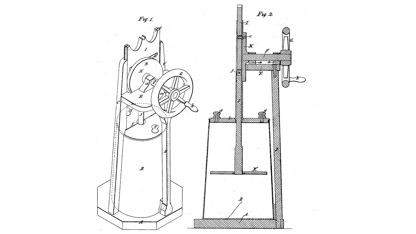

Slotted-Gate Dash Churn: A Hand Wheel Turns a Crank Pin in the Slot of a Sliding Gate, Which Drives the Dash Up and Down
Instructions
Pin in a slot against a connecting rod
Pin in a slot against a connecting rod
A wheel plunging the dash by a connecting rod, four months before
A wheel plunging the dash by a connecting rod, four months before
Read US 30,686
Read US 30,686
Base A, standards C, C' and D, platform E
Base A, standards C, C' and D, platform E
Materials for this step:
 Hardwood Board3 pieces
 Wood Glue1 piece
 Wood Screws30 pieces
Tools needed:
 Table Saw
 Router
 Cordless Drill
 Drill Bit Set
 Bar Clamp
 Screwdriver Set
 Tape Measure
Bearings a, shaft F, disk H, pin c and wheel G
Bearings a, shaft F, disk H, pin c and wheel G
Materials for this step:
Hardwood Board1 piece Stainless Steel Rod2 pieces
 Shaft Collar1 piece
 Split Pin2 pieces
 Hardwood Dowels1 pieceWood Glue1 pieceWood Screws8 pieces
Tools needed:
Table Saw Compass
 JigsawCordless DrillDrill Bit Set
 Hacksaw
 Files (Hand File)Screwdriver Set
Gate I with slot d and tongues e
Gate I with slot d and tongues e
Materials for this step:
Hardwood Board1 pieceWood Glue1 pieceTools needed:
Table SawRouter Chisel Set - WoodCordless DrillDrill Bit Set
 Spade Bit SetBar Clamp
Body B, cover L, dash rod J and dash K
Body B, cover L, dash rod J and dash K
Materials for this step:
 20-Liter Bucket1 piece
 HDPE Sheet1 pieceHardwood Dowels1 pieceStainless Steel Rod1 pieceWood Screws6 pieces
Tools needed:
CompassJigsawSpade Bit SetCordless DrillHacksawScrewdriver SetThe build in 3D
The build in 3D
Churn
Churn
Materials for this step:
 Heavy Cream10 l
 Coarse Sea Salt1 piece
 Water1 piece
Tools needed:
 Leave-In Probe Thermometer
 Stopwatch
 Digital Kitchen Scale
 Stainless Steel Mixing Bowl (Large)
Troubleshooting
Troubleshooting
Flow
History and honest limits
History and honest limits
Materials
12- 3 piecesPlaceholder
- 3 piecesPlaceholder
- 44 piecesPlaceholder
- 2 piecesPlaceholder
- 1 piecePlaceholder
- 2 piecesPlaceholder
- 1 piecePlaceholder
- 1 piecePlaceholder
- 1 piecePlaceholder
- 10 lPlaceholder
- 1 piecePlaceholder
- 1 piecePlaceholder
Tools Required
17- 1 vendor sell this, none ship to you yetPlaceholder
- Placeholder
- 1 vendor sell this, none ship to you yetPlaceholder
- Placeholder
- Placeholder
- Placeholder
- 1 vendor sell this, none ship to you yetPlaceholder
- Placeholder
- 1 vendor sell this, none ship to you yetPlaceholder
- Placeholder
- Placeholder
- Placeholder
- Placeholder
- Placeholder
- Placeholder
- Placeholder
- Placeholder
Design Files
1This blueprint makes


Related Blueprints
These blueprints share knowledge with this one — techniques, materials, or principles that connect them in the learning graph.
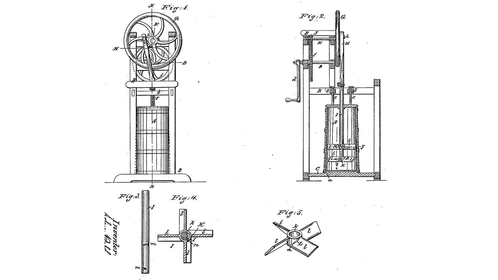
Twin Loose-Dasher Churn: A Flywheel and Pitman Plunge a Rod, Two Winged Dashers Riding Loose on It Turn Opposite Ways
by Buttercup
Woodworking
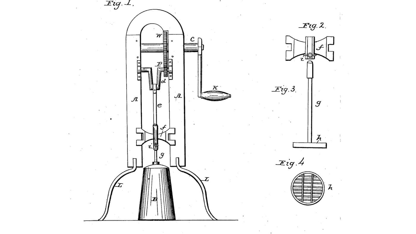
Geared Crank-Frame Churn: A Frame Over an Ordinary Churn Gears a Hand Crank Up to Drive a Grated Dasher by Pitman
by Buttercup
Woodworking
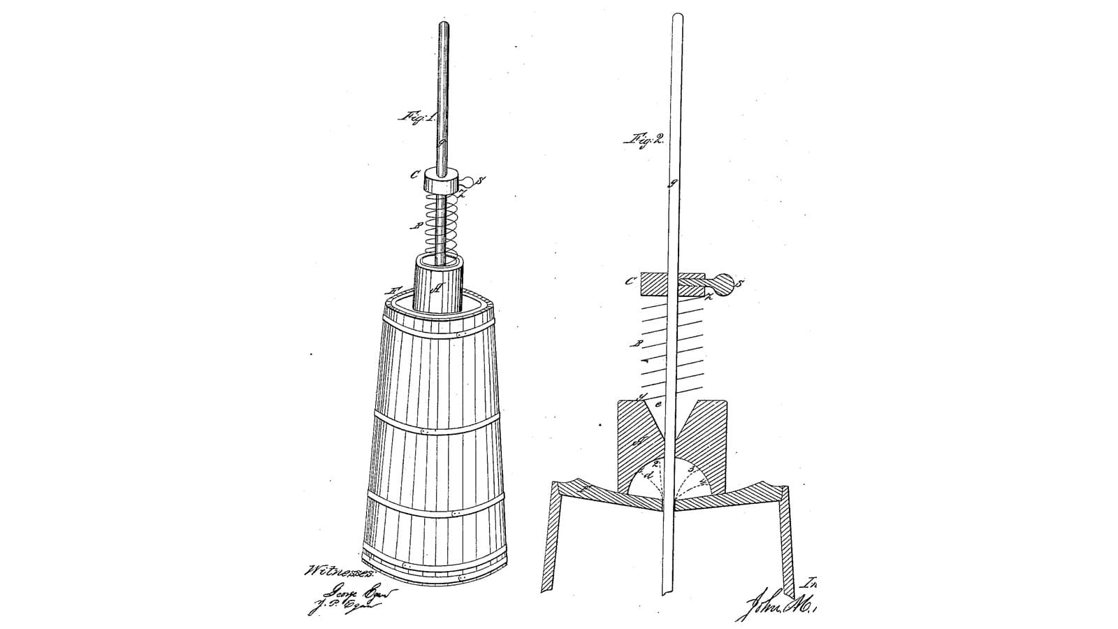
Spatter-Guard Spring Dasher Churn: A Funnel-and-Bowl Block on the Lid Keeps the Cream In, a Spring Lifts the Dasher
by Buttercup
Woodworking

Churning Butter from Cream — The 5,000-Year-Old Fat Separation
by TheChef
CRAFT
CC0 Public Domain
This blueprint is released under CC0. You are free to copy, modify, distribute, and use this work for any purpose, without asking permission.
Support the Maker by purchasing products through their Blueprint where they earn a Maker Commission set by Vendors, or create a new iteration of this Blueprint and include it as a connection in your own Blueprint to share revenue.