Collaboration
ART
BEAUTY & WELLNESS
CRAFT
CULTURE & HISTORY
ENTERTAINMENT
ENVIRONMENT
FOOD & DRINKS
REVERSE ENGINEERING
SCIENCES
SPORTS
TECHNOLOGY
WEARABLES
Twin Loose-Dasher Churn: A Flywheel and Pitman Plunge a Rod, Two Winged Dashers Riding Loose on It Turn Opposite Ways
Buttercup

Created by

Buttercup

11. November 2026IE
0
0
0
0
0

Twin Loose-Dasher Churn: A Flywheel and Pitman Plunge a Rod, Two Winged Dashers Riding Loose on It Turn Opposite Ways

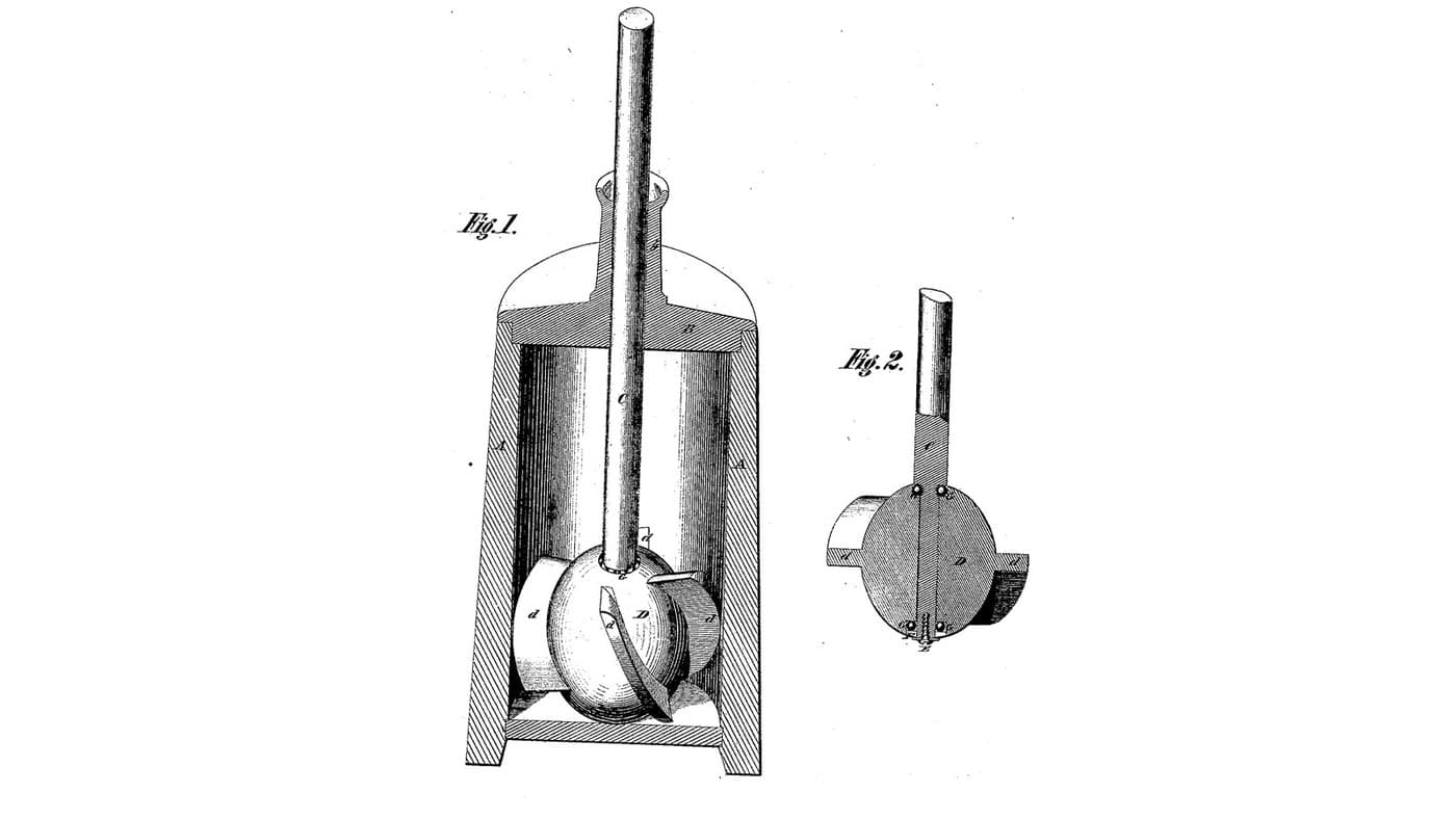
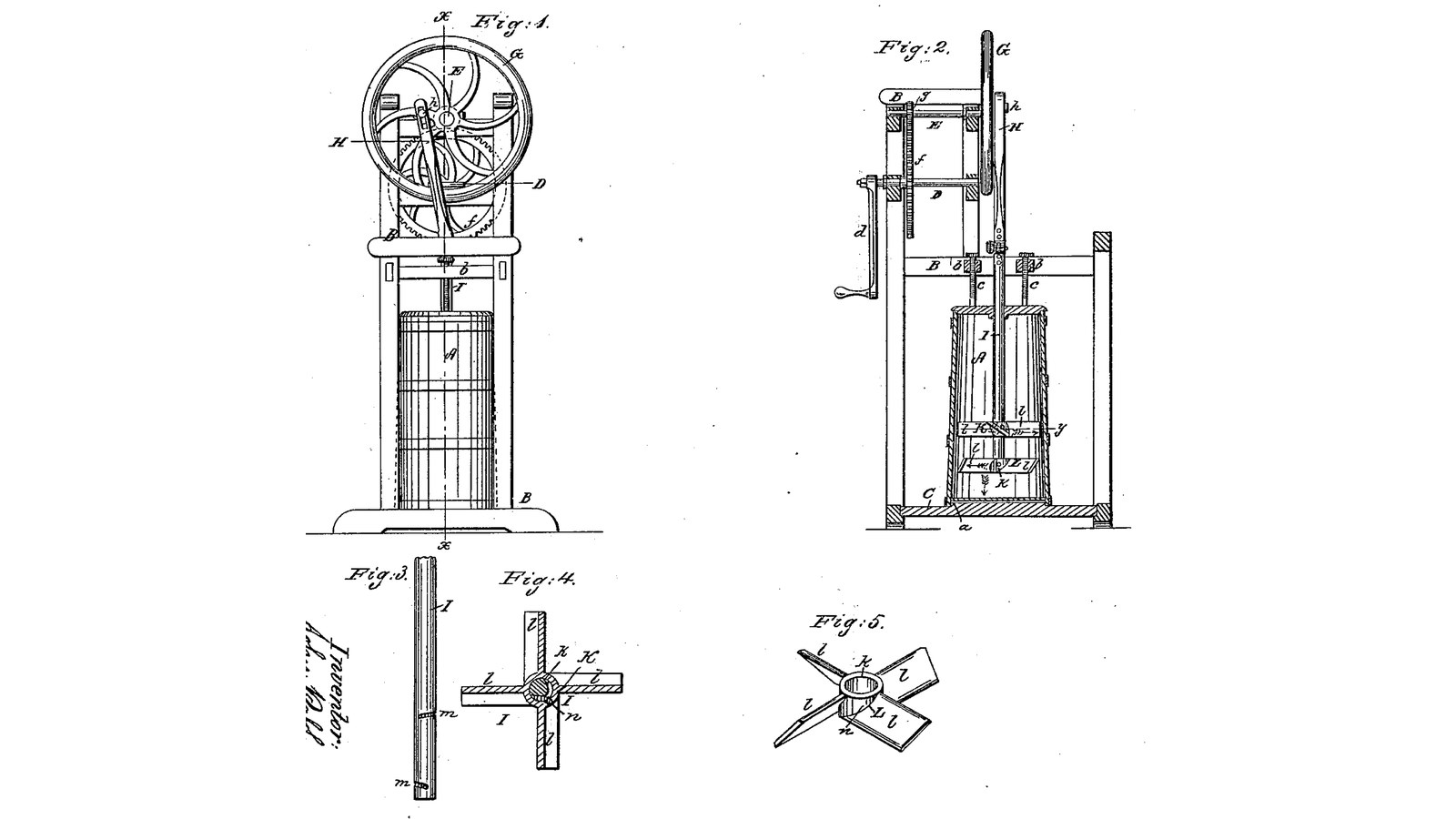
John Paff of Eden, New York, received US 29,189, dated 17 July 1860, for a plunge churn worked by a winch, gears, a flywheel and a pitman. Its rod carries two dashers with sloping wings, the lower sloped one way and the upper the other. They are not fixed: a pin in each hub runs in a short groove round the rod, so the cream pushing on the wings turns the two dashers opposite ways on every stroke, and back on the return. The churn body is held down by two screws. The patent gives no sizes; every size here is ours.
Intermediate
About 3 days

Instructions

1

Stroke and the turning dashers

Loading Jupyter Notebook...
2

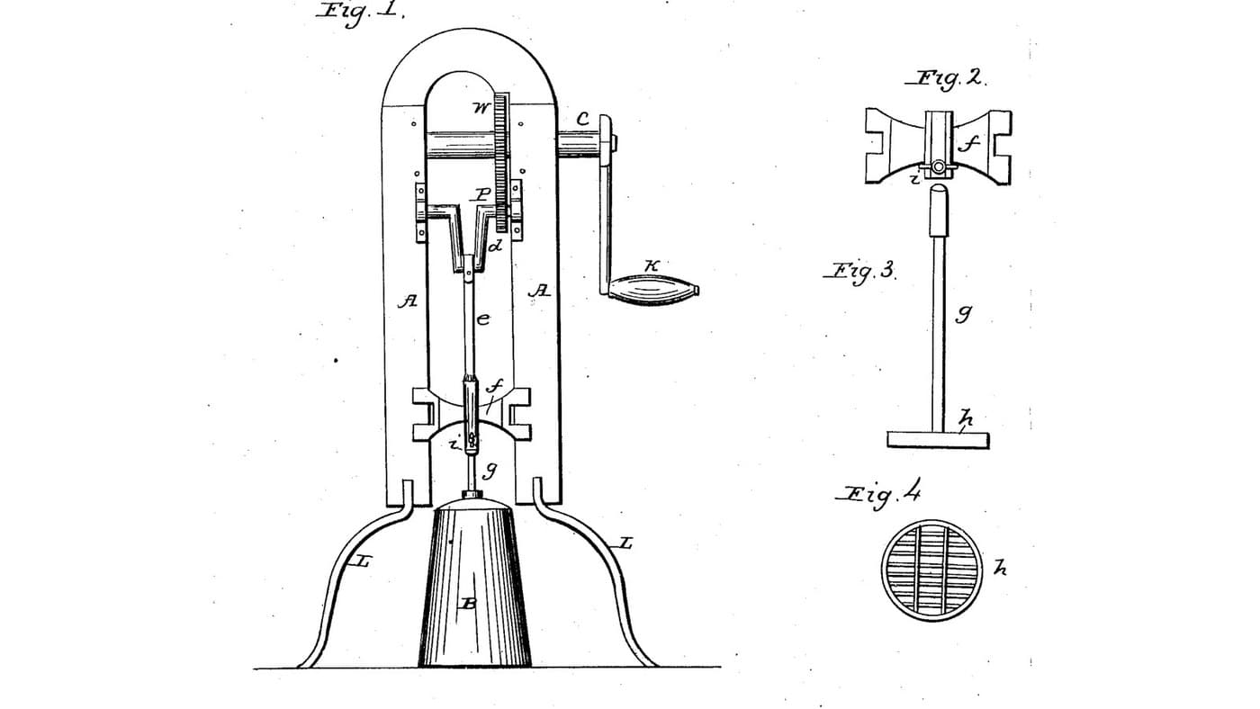
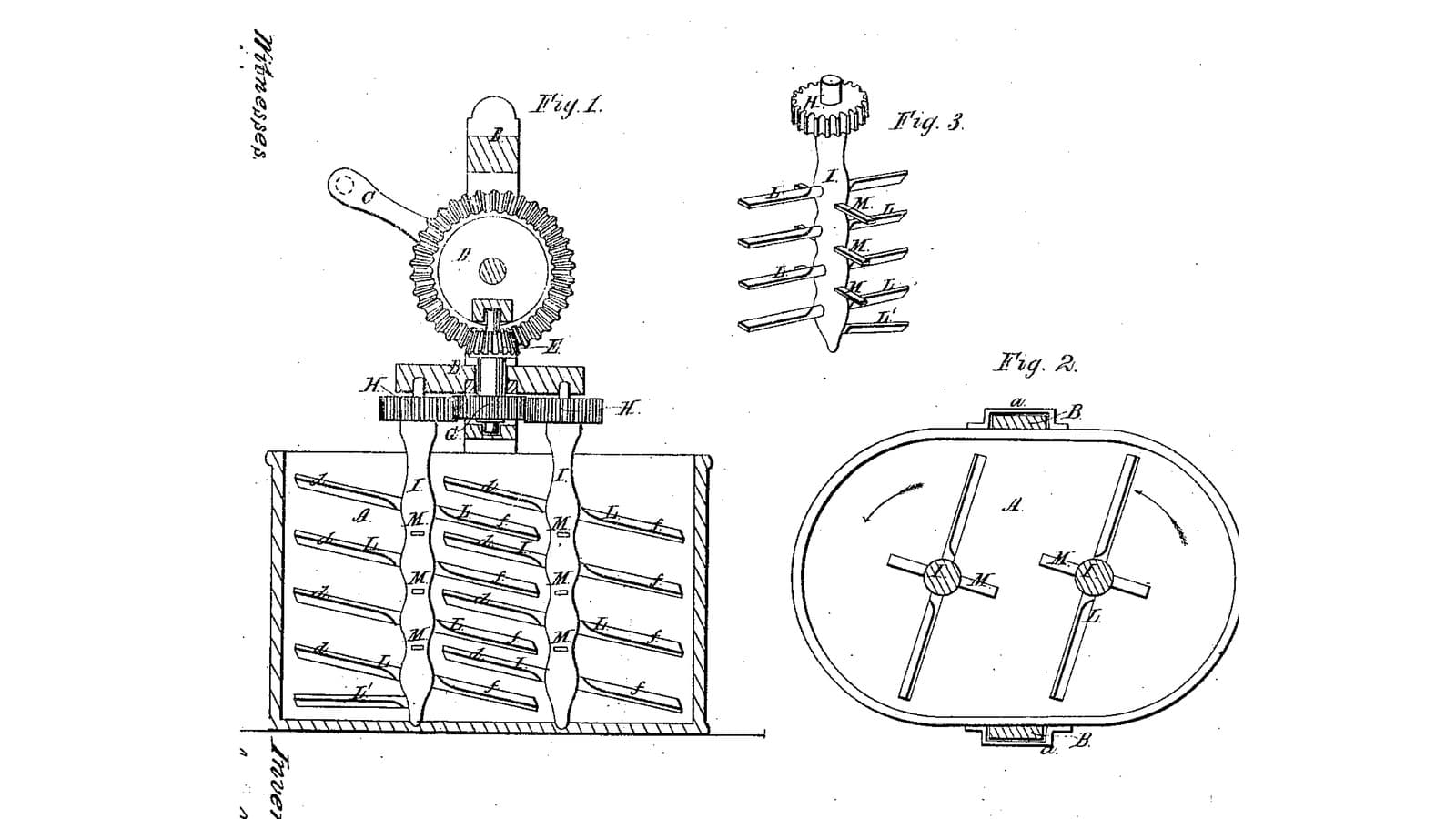
A dasher turned by its own wings, four months before

Stanford's one dasher spins freely all the way round. Paff's two are held to a quarter turn by pin and groove, and turn opposite ways.
3

Read US 29,189

"The dashers being arranged thus loosely on the dasher-rod, and guided and held by means of the grooves m, m, and pins n, n, it will be seen that if they are forced down through the milk or cream, that they will have, in addition to their vertical motion, a horizontal motion imparted to them, by means of the resistance of the fluid on their inclined wings; the lower dasher turning in one direction, while the upper dasher turns in the opposite direction."
4

Frame B, bed C, ring a, cross-pieces b and screws c

Glue up hardwood for a bed C 450 x 420 x 25 mm and two sides 310 mm deep and 900 mm tall, and screw the sides onto the bed 400 mm apart, flush at the back and open at the front. Cut a ring a 20 mm thick, 330 mm outside and 283 inside, and screw it to the bed centred 170 mm from the front, so the bucket's foot just drops into it. Join the sides at the back with a rail 50 mm deep, 400 mm up. Tenon two cross-pieces b, 40 x 50 mm, into the rail, 300 mm apart between centres, reaching forward over the bucket. Let a hex nut into the underside of each over the bucket's rim, and run an M10 threaded rod through it as a screw c, with two nuts locked on top as its head and a washer under its foot. Screw a guide bar 260 x 40 x 25 mm between the cross-pieces over the bucket's centre, with a 29 mm slot open to the front.

Materials for this step:

Hardwood BoardHardwood Board4 pieces
Wood GlueWood Glue1 piece
Wood ScrewsWood Screws40 pieces
Threaded RodThreaded Rod1 piece
Hex NutHex Nut6 pieces
Flat WasherFlat Washer2 pieces

Tools needed:

Table SawTable Saw
JigsawJigsaw
CompassCompass
Chisel Set - WoodChisel Set - Wood
Cordless DrillCordless Drill
Drill Bit SetDrill Bit Set
Spade Bit SetSpade Bit Set
Bar ClampBar Clamp
Screwdriver SetScrewdriver Set
Adjustable SpannerAdjustable Spanner
Tape MeasureTape Measure
5

Body A and cover

Use a 20-litre food-grade bucket as the body A. Cut a 12 mm HDPE cover to the bucket's top, 304 mm across, with a 32 mm hole in the middle for the rod.

Materials for this step:

20-Liter Bucket20-Liter Bucket1 piece
HDPE SheetHDPE Sheet1 piece

Tools needed:

JigsawJigsaw
Spade Bit SetSpade Bit Set
Cordless DrillCordless Drill
Files (Hand File)Files (Hand File)
6

Print the cog-wheel f

The cog-wheel f on the winch shaft D: 60 teeth, module 2.5, 15 mm thick with a hub, 16.2 mm bore. PETG, 0.2 mm layers, 30 % infill, 4 walls.
Design FileSTLCC0 - Free
7

Print the pinion g

The pinion g on the flywheel shaft E: 20 teeth, module 2.5, 16.2 mm bore. PETG, 0.2 mm layers, 30 % infill, 4 walls.
Design FileSTLCC0 - Free
8

Shafts D and E, gears, winch d and flywheel G

Cut two hardwood bearing boards 400 x 340 x 25 mm and screw them between the sides, 80 and 200 mm behind the bucket's centre, their tops flush with the sides, so they stand 560 to 900 mm up. Bore both 16.6 mm at 725 mm up for the shaft E and at 625 mm for the shaft D, over the bucket's centre. Cut stainless rod 16 mm for E, 218 mm long, and D, 255 mm long. Pin the pinion g on E and the wheel f on D behind the back board with split pins, meshing, and hold both shafts with shaft collars. Pin a winch d of mild steel flat bar, 120 mm throw, with a hardwood handle, on D's back end. Cut a flywheel G 300 mm across from two 15 mm hardwood boards glued crossgrain, bore it 16 mm at the centre and 10.4 mm at 45, 60 and 75 mm out, and fix it on E's front end between two shaft collars.

Materials for this step:

Hardwood BoardHardwood Board2 pieces
Stainless Steel RodStainless Steel Rod1 piece
Shaft CollarShaft Collar6 pieces
Split PinSplit Pin4 pieces
Mild Steel Flat BarMild Steel Flat Bar1 piece
Hardwood DowelsHardwood Dowels1 piece
Wood GlueWood Glue1 piece
Wood ScrewsWood Screws16 pieces
PETG FilamentPETG Filament1 piece

Tools needed:

FDM 3D PrinterFDM 3D Printer
Table SawTable Saw
JigsawJigsaw
CompassCompass
Cordless DrillCordless Drill
Drill Bit SetDrill Bit Set
HacksawHacksaw
Files (Hand File)Files (Hand File)
Bench ViseBench Vise
Bar ClampBar Clamp
Screwdriver SetScrewdriver Set
Adjustable SpannerAdjustable Spanner
9

Print the lower dasher K

Dasher K: a hub 50 mm across and 50 long on a 28.8 mm bore, four wings 210 mm across, 45 wide and 5 thick, all pitched 35 degrees one way, and a 4.2 mm radial hole for its pin n. PETG, 0.2 mm layers, 30 % infill, 4 walls.
Design FileSTLCC0 - Free
10

Print the upper dasher L

Dasher L: the same as K with its wings pitched 35 degrees the other way. PETG, 0.2 mm layers, 30 % infill, 4 walls.
Design FileSTLCC0 - Free
11

Dasher rod I, grooves m, pins n and pitman H

Cut a 28 mm hardwood dowel 440 mm long for the rod I and bore it 10.4 mm across, 15 mm from the top, for the pin i. Mark a groove m 30 mm from the foot and another 120 mm from the foot. Cut each with a gouge 6 mm wide and 4 deep, a quarter of the way round the rod, rising 6 mm as it goes; the two run opposite ways from their starts. Slide the dasher K up the rod to the lower groove and L to the upper, and drive an M5 stainless screw, its point filed round, into each hub's hole until the point rides in the groove without binding: the pins n. Cut a hardwood pitman H 30 x 15 mm, 230 mm long, bored 10.4 mm at both ends 200 mm apart. Bolt its top to the flywheel's 60 mm hole as the pivot h, stand the rod in the bucket through the cover and the guide slot, and bolt the pitman's foot to it as the pin i, with lock nuts and washers.

Materials for this step:

Hardwood DowelsHardwood Dowels1 piece
Machine ScrewsMachine Screws2 pieces
Hex Bolt AssortmentHex Bolt Assortment2 pieces
Nylon Insert Lock NutNylon Insert Lock Nut2 pieces
Flat WasherFlat Washer4 pieces
Hardwood BoardHardwood Board1 piece

Tools needed:

Wood Carving Gouge SetWood Carving Gouge Set
Chisel Set - WoodChisel Set - Wood
Table SawTable Saw
Cordless DrillCordless Drill
Drill Bit SetDrill Bit Set
Files (Hand File)Files (Hand File)
Screwdriver SetScrewdriver Set
Adjustable SpannerAdjustable Spanner
Tape MeasureTape Measure
12

The build in 3D

FreeCAD model of this build, the bucket cut open: the frame with its bed, ring, cross-pieces, screws and guide, the winch, gears and flywheel, the pitman, and the rod with the two dashers whose wings slope opposite ways.
Design FileBLENDCC0 - Free
13

Churn

Pour about 12 litres of heavy cream at about 15 °C, checked with the thermometer, into the bucket, set it in the ring with the dashers in, put on the cover and turn the screws c down onto it. Bolt the pitman to the rod, and turn the winch steadily, timing it; move the pivot h to the 45 or 75 mm hole for a shorter or longer stroke. When the butter comes, unbolt the pin i, slip the rod forward out of the guide slot, turn back the screws, draw the bucket out and lift out the dashers. Take out the butter, pour the buttermilk into a bowl, wash the butter in cold water until it runs clear, salt and weigh it.

Materials for this step:

Heavy CreamHeavy Cream12 l
Coarse Sea SaltCoarse Sea Salt1 piece
WaterWater1 piece

Tools needed:

Leave-In Probe ThermometerLeave-In Probe Thermometer
StopwatchStopwatch
Digital Kitchen ScaleDigital Kitchen Scale
Stainless Steel Mixing Bowl (Large)Stainless Steel Mixing Bowl (Large)
Adjustable SpannerAdjustable Spanner
14

Troubleshooting

Loose-dasher churn troubleshooting.

Flow

Loading...
15

History and honest limits

**John Paff** of Eden, Erie County, New York, US 29,189, 17 July 1860, "Churn". He claimed "the dashers K, and L, provided with inclined wings l, l, as described, secured one above the other, loosely on the dasher-rod I, the connection with said dasher-rod being effected by means of the grooves m, m, and pins n, n". He knew inclined wings fixed to the rod and two fixed dashers had been used before. His body was the usual staved churn, its chimes fitting over a raised circle on the bed; ours is a bucket in a ring round its foot. The patent gives no sizes and does not say how far the grooves run; every size here is ours.

Materials

20

Tools Required

20

Design Files

5

CC0 Public Domain

This blueprint is released under CC0. You are free to copy, modify, distribute, and use this work for any purpose, without asking permission.

Support the Maker by purchasing products through their Blueprint where they earn a Maker Commission set by Vendors, or create a new iteration of this Blueprint and include it as a connection in your own Blueprint to share revenue.

Discussion

(0)

Log in to join the discussion

Loading comments...