Collaboration
ART
BEAUTY & WELLNESS
CRAFT
CULTURE & HISTORY
ENTERTAINMENT
ENVIRONMENT
FOOD & DRINKS
REVERSE ENGINEERING
SCIENCES
SPORTS
TECHNOLOGY
WEARABLES
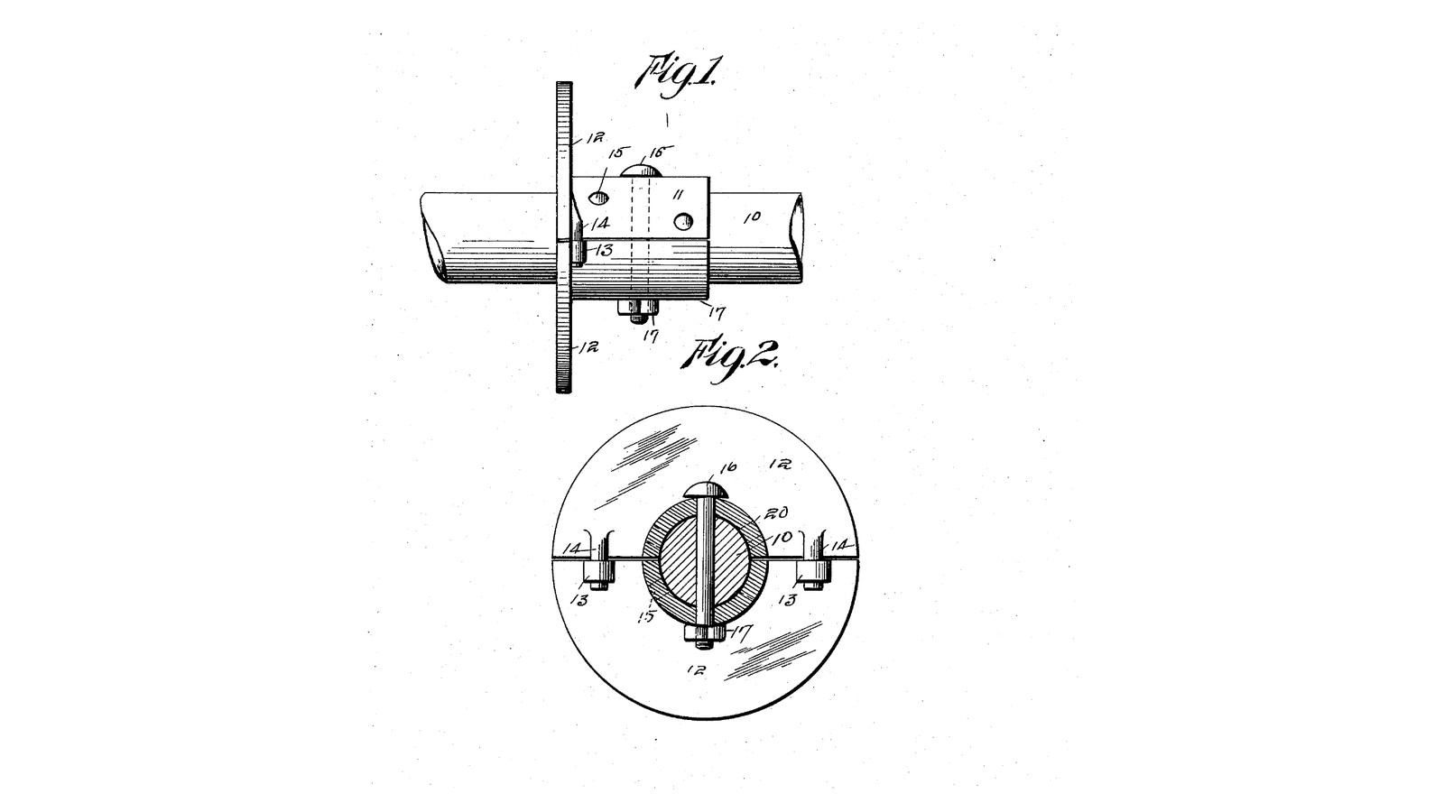


Divisible Flanged Shaft Collar: Two Halves Locked by Lugs, Bolted Through the Shaft in One of Three Hole Pairs (Obey, 1916)
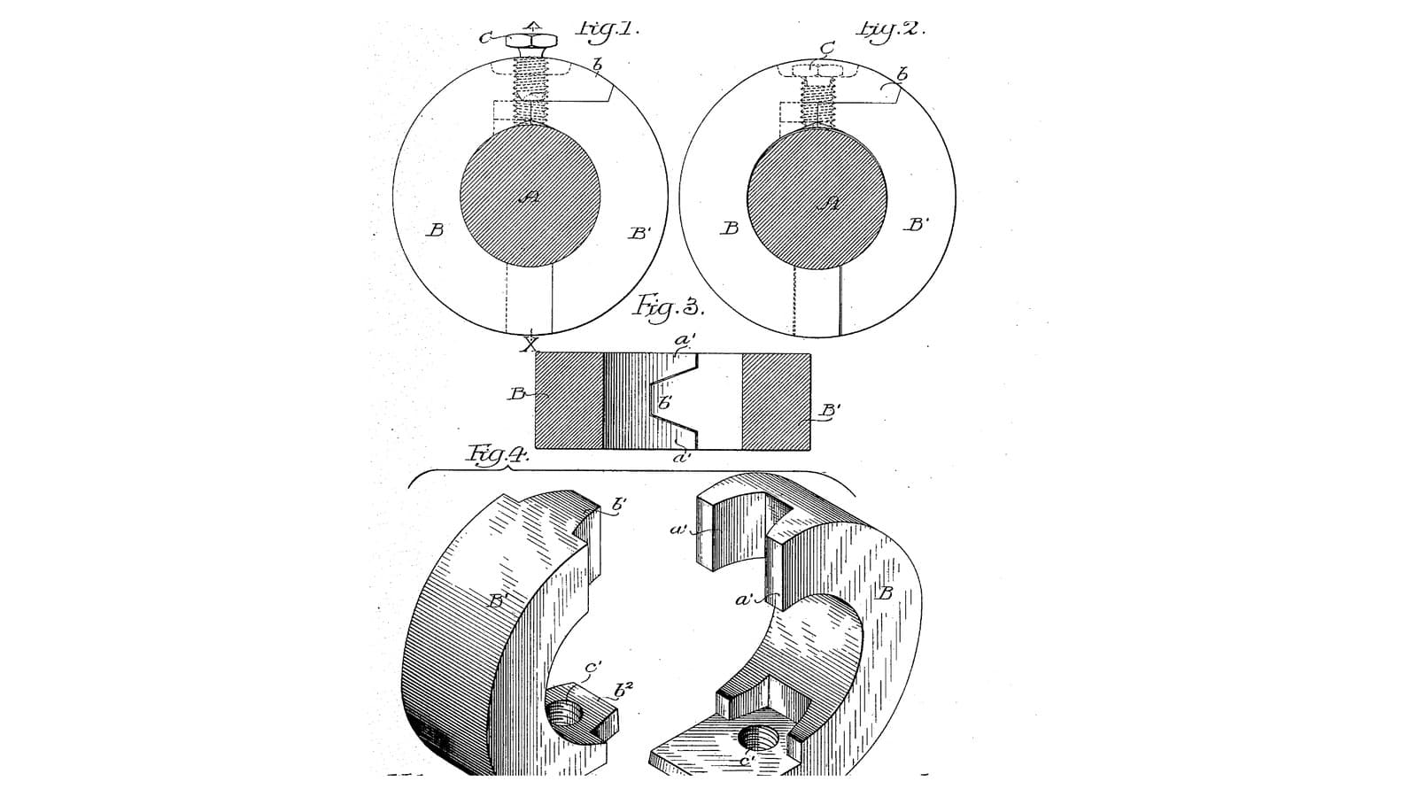
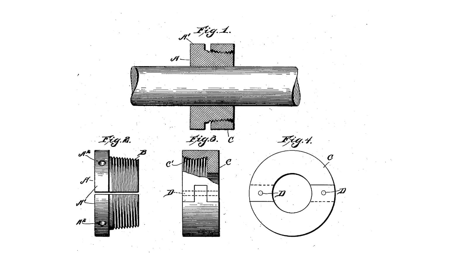
James F. Obey of Centerville, Iowa, received US 1,201,863, dated 17 October 1916, for a flanged collar that comes in two halves. It was meant for the chain rods of railway dump cars, whose collars often broke, and a whole rod then had to come out of its bearings. Lugs on one half of the flange go into slots in the other. A bolt through the rod's own hole and through a pair of openings in the collar holds it, with a nut. The collar has several pairs at different places, so it can be set in more than one position.
We turn ours in one piece and saw it in half. The patent gives no sizes; every size here is ours.
Intermediate
About 6 hours
Instructions
1
1
Where each pair of openings puts the collar
Where each pair of openings puts the collar
Loading Jupyter Notebook...
2
2
Read US 1,201,863
Read US 1,201,863
"These shaft collars frequently become broken and it is one of the important purposes of my invention to provide a shaft-collar which can be quickly and easily installed on the shaft without the removal of the shaft from its bearings."
3
3
Turn the flanged collar
Turn the flanged collar
Grip 75 mm round bar in the 3-jaw chuck. Face it and turn the flange to 70 mm. Turn the hub to 32 mm for 40 mm, leaving the flange 10 mm thick. Centre-drill, drill through 15 mm and ream 16 mm. Part off at 50 mm and face the flange's outer face.
Materials for this step:
 Mild Steel Round Bar1 piece
 Cutting Oil1 piece
Tools needed:
 Metal Lathe
 Lathe Chuck 3-Jaw
 Lathe Cutting Tool
 Parting Tool
 Center Drill Set
 Drill Bit Set
 Reamer
 Digital Caliper 6-Inch
 Safety Glasses
4
4
Mark out and drill the holes
Mark out and drill the holes
Blue the flange and hub. Scribe the split line across the flange through the centre and along both sides of the hub. Mark two chord holes across the split line, 28 mm each side of the centre, in the middle of the flange's thickness; drill them 5 mm right through the flange, square to the split line. Mark three pairs of openings round the hub, at 18, 30 and 42 mm from the flange's outer face and at 90, 30 and 150 degrees from the split line. Centre-punch, and with the collar in the V-block drill each pair 6.5 mm straight through the hub and the bore.
Tools needed:
 Engineer's Blue
 Scriber
 Combination Square
 Protractor
 Center Punch
 Drill Press
 Machine Vice
 V-BlockDrill Bit SetDigital Caliper 6-Inch
5
5
Saw it in half and fit the lugs
Saw it in half and fit the lugs
In soft jaws, saw down the split line through flange and hub with a fine hacksaw blade, through the middle of the chord holes. File the cut faces flat. Tap a 5 mm steel dowel pin 20 mm long into each chord hole of one half, leaving 9 mm sticking out: these are the lugs, and the other half's holes are the slots. Put the halves together: they must close with only the saw cut between them, and slide apart only straight.
Materials for this step:
 Steel Dowel Pin2 pieces
Tools needed:
 Bench Vise
 Vice Soft Jaws
 Hacksaw
 File Set
 Ball Peen Hammer
 Deburring Tool
6
6
The collar in 3D
The collar in 3D
FreeCAD model, our sizes: the two halves with flange and hub on a 16 mm shaft, the two pins across the split in the flange, the three pairs of openings, and the M6 bolt and nut through the first pair and the shaft.
7
7
Drill the shaft and fit the collar
Drill the shaft and fit the collar
Mark where the collar's flange must stand and drill a 6.5 mm hole straight across the shaft, 18 mm from that mark, with the shaft in the V-block. Put the two halves round the shaft from the sides, the lugs into the slots, and turn the collar until the 18 mm pair lines up with the hole. Push an M6 x 50 bolt through and tighten a nyloc nut on it. To move the collar, take the bolt out, slide and turn the collar until another pair lines up, and bolt it again.
Materials for this step:
 Hex Bolt Assortment1 piece
 Nylon Insert Lock Nut1 piece
Tools needed:
Drill PressV-BlockDrill Bit SetCenter Punch Adjustable Spanner
8
8
Troubleshooting
Troubleshooting
Obey collar troubleshooting.
Flow
Loading...
9
9
History and honest limits
History and honest limits
**James F. Obey** of Centerville, Appanoose County, Iowa, US 1,201,863, dated 17 October 1916, filed 3 August 1915. He claimed a shaft with a transverse hole, "a collar mounted thereon consisting of a longitudinally halved cylinder with an annular flange at one end, one half of the flange being provided with lugs, the other half being provided with corresponding slots", pairs of aligned openings at different points along and round the cylinder, and a bolt through the shaft's hole and a chosen pair. His lugs are bent pieces on the face of the flange that hook into yokes on the other half; ours are pins in holes through the flange, which do the same job. His bolt has a round head; ours is a hex bolt with a nyloc nut. The patent gives no sizes or material; every size here is ours.
Materials
5- 1 piecePlaceholder
- 1 piecePlaceholder
- 2 piecesPlaceholder
- 1 piecePlaceholder
- 1 piecePlaceholder
Tools Required
24- Placeholder
- Placeholder
- Placeholder
- Placeholder
- Placeholder
- Placeholder
- Placeholder
- Placeholder
- Placeholder
- Placeholder
- Placeholder
- Placeholder
- Placeholder
- Placeholder
- Placeholder
- Placeholder
- Placeholder
- Placeholder
- Placeholder
- Placeholder
- Placeholder
- Placeholder
- Placeholder
- Placeholder
Design Files
1This blueprint makes
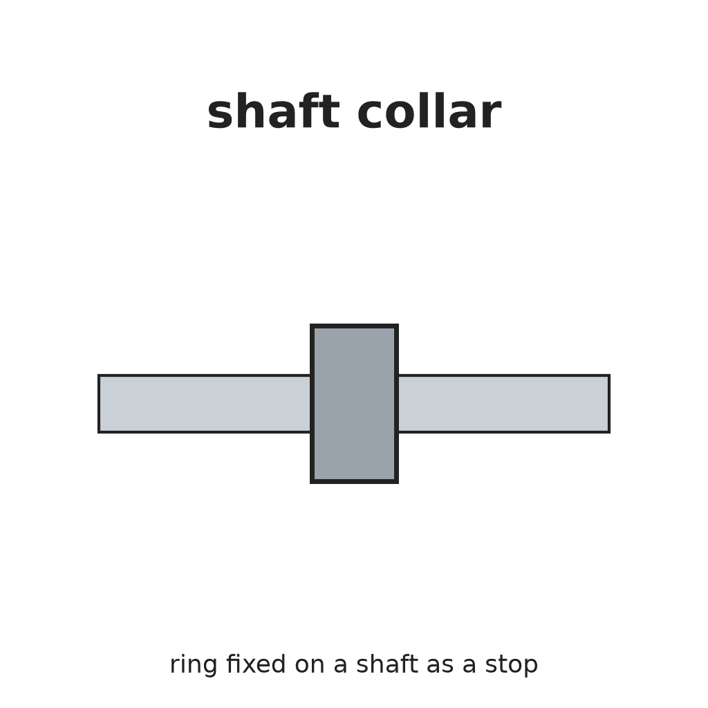
Related Blueprints
These blueprints share knowledge with this one — techniques, materials, or principles that connect them in the learning graph.
CC0 Public Domain
This blueprint is released under CC0. You are free to copy, modify, distribute, and use this work for any purpose, without asking permission.
Support the Maker by purchasing products through their Blueprint where they earn a Maker Commission set by Vendors, or create a new iteration of this Blueprint and include it as a connection in your own Blueprint to share revenue.