ART
BEAUTY & WELLNESS
CRAFT
CULTURE & HISTORY
ENTERTAINMENT
ENVIRONMENT
FOOD & DRINKS
REVERSE ENGINEERING
SCIENCES
SPORTS
TECHNOLOGY
WEARABLES
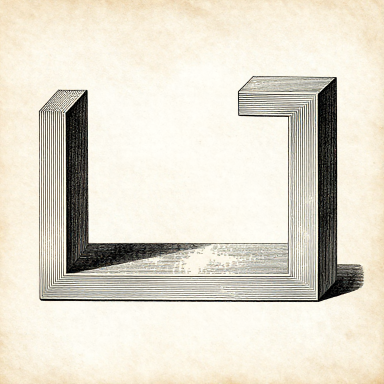


Orientation: A Printed Part Is Weakest Between Its Layers
An FDM part is not one piece of plastic. It is a stack of welded layers, and the weld between layers is weaker than the plastic within a layer — typically by half.
So a printed part has a grain, exactly as timber does, and the same rule applies: find out which way the load runs and put the strong direction there. A hook printed lying down carries several times the load of the identical hook printed standing up.
Orientation also decides where the supports go, which surfaces come out smooth, and how long it takes. It is the single highest-leverage decision in preparing a print, and it costs nothing but a moment's thought before slicing.
Intermediate
3 hours
Instructions
1
1
Find the load path first
Find the load path first
Before orienting anything, ask what the part will actually have to resist. A bracket carries a bending load along its arm; a clip is bent open repeatedly; a spacer is squeezed.
Then lay the part so the layers run ALONG the direction the load pulls, not across it. A tensile load pulling layer from layer is the one case where the weld is the only thing holding — and that is the case to avoid.
Where the part has to be strong in two directions at once, it may be better printed in two pieces and joined, or printed at 45 degrees as a compromise. Recognising that a single orientation cannot satisfy both is the useful step.
Materials for this step:
 3D Printing Filament (PLA)1 piece
Tools needed:
 3MF File Slicer Software
 Desktop Computer
2
2
What the anisotropy actually costs
What the anisotropy actually costs
Loading Jupyter Notebook...
Materials for this step:
3D Printing Filament (PLA)1 piece Carbon Fiber PETG Filament1 piece
Tools needed:
Desktop Computer3MF File Slicer Software Digital Caliper 6-Inch
3
3
Orientation also decides which surfaces are good
Orientation also decides which surfaces are good
The face touching the plate comes out flat and smooth. Top faces come out smooth if they have enough solid layers. Slanted and curved faces show stepping, because a curve is being approximated by a stack of flat layers.
So put the face that matters — the one that will be seen, or that has to seal — flat against the plate or horizontal at the top. Everything else is a compromise made deliberately.
Holes are the special case. A hole whose axis is VERTICAL comes out round and accurate; a hole printed with its axis horizontal comes out as an arch that sags at the top and is measurably out of round. Orienting for holes is often worth more than orienting for appearance.
Materials for this step:
3D Printing Filament (PLA)1 pieceTools needed:
3MF File Slicer SoftwareDigital Caliper 6-Inch Magnifying Loupe
4
4
Test it rather than reasoning about it
Test it rather than reasoning about it
Print the same small part in two orientations and break them both. It takes an hour and it settles the question for your printer, your filament and your settings — which published figures cannot.
Break them the same way, with the same lever arm, and note what force it took, even roughly. Two readings that differ by a factor of two are unambiguous; two that differ by 10% are within the noise and need repeating.
Keep the broken pieces and look at the fracture. A break that follows a clean layer line across the whole face is a layer adhesion failure; a ragged break through the material is the plastic itself giving way, which means orientation is no longer the limiting factor.
Materials for this step:
3D Printing Filament (PLA)1 pieceTools needed:
 FDM 3D PrinterMagnifying LoupeDigital Caliper 6-Inch
Materials
2- 4 piecesPlaceholder
- Carbon Fiber PETG Filament10% commission1 piecePlaceholder
Related Blueprints
These blueprints share knowledge with this one — techniques, materials, or principles that connect them in the learning graph.



CC0 Public Domain
This blueprint is released under CC0. You are free to copy, modify, distribute, and use this work for any purpose, without asking permission.
Support the Maker by purchasing products through their Blueprint where they earn a Maker Commission set by Vendors, or create a new iteration of this Blueprint and include it as a connection in your own Blueprint to share revenue.