ART
BEAUTY & WELLNESS
CRAFT
CULTURE & HISTORY
ENTERTAINMENT
ENVIRONMENT
FOOD & DRINKS
REVERSE ENGINEERING
SCIENCES
SPORTS
TECHNOLOGY
WEARABLES
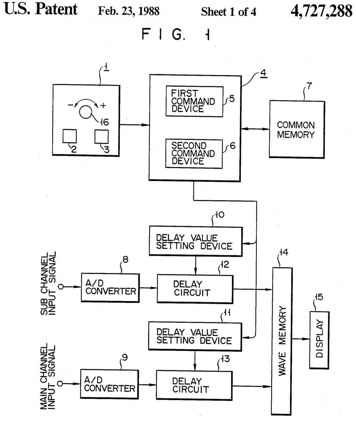


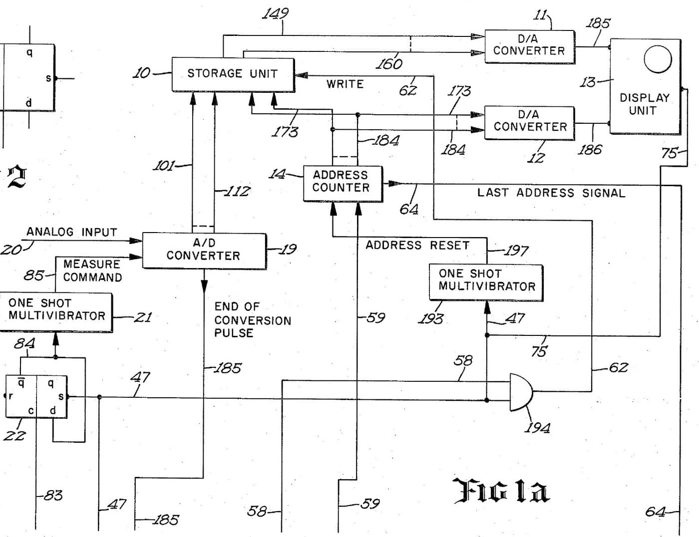
Oscilloscope: Two-Channel Digital, with a Delay per Channel and a Common Delay (Anritsu, US 4,727,288, 1988)
A two-channel digital oscilloscope. Each channel has its own converter and delay circuit. One knob, with a main and a sub button, sets the delays. The sub button shifts only the sub channel's wave, so you can line it up against the main one. The main button shifts both waves together and keeps the gap between them.
Result: a 2-channel digital oscilloscope that can move both traces along the time base without losing their phase difference.
Source: K. Nakatsugawa et al. (Anritsu), US 4,727,288 (1988). Unknown: sample rate, bandwidth, memory size and the display. Picture: the patent drawing.
Expert
Unknown
Instructions
1
1
Convert the two channels
Convert the two channels
Bring the main channel and the sub channel each to its own analog-to-digital converter. Ours: BNC sockets. Not given: the sample rate, the bandwidth.
Materials for this step:
 Analog-to-Digital Converter2 main and sub converters
 Coaxial Connector Set (BNC / SO-239)1 input sockets
Tools needed:
 Soldering Iron
 Wire Strippers
2
2
Delay, store and display
Delay, store and display
Pass each channel's digital signal through its own delay circuit, whose delay is set by its own delay value setting device. Store both delayed signals in a wave memory and show them on the display. Ours: logic ICs for the delay circuits and setting devices, IC memory, and a CRT driven through D/A converters. Not given: how the delay circuits are built, the memory size, the display.
Materials for this step:
 Logic IC Assortment1 delay circuits and setting devices
 Integrated-Circuit Memory1 wave memory
 Digital-to-Analog Converter2 display drive
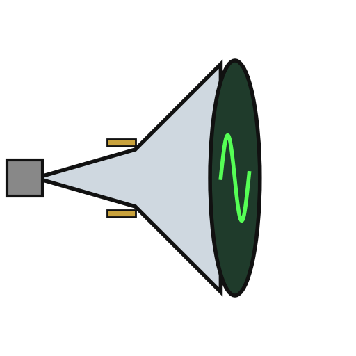 Cathode-Ray Tube1 display
Tools needed:
Soldering IronWire Strippers3
3
Build the delay panel and processor
Build the delay panel and processor
Make a delay operation panel with a main switch, a sub switch and one dial, with an encoder on the dial so each turn is read as a change in its output. Connect the panel to a microprocessor with a common memory that holds the sub channel's delay S in one area and the main channel's delay M in another. Mount it all in a case with its supply. Ours: push buttons, an aluminium case, a DC supply.
Materials for this step:
 Push Button2 main and sub switches
 Rotary Encoder1 delay dial
 Microprocessor1 command devicesIntegrated-Circuit Memory1 common memory
 Aluminium Enclosure Box1 case
Tools needed:
 DC Power Supply
 Drill PressSoldering Iron
4
4
Program the two commands
Program the two commands
When the dial turns, read the encoder change e and which switch is held. Sub switch: add e to S, set the sum in the sub channel's setting device and store it back as the new S. Main switch: add e to both M and S, set M + e in the main channel's device and S + e in the sub channel's, and store both back. The main command so moves both channels by the same amount and keeps their relative delay.
Tools needed:
Soldering Iron5
5
Compare two waves
Compare two waves
Feed two signals in. Hold the sub switch and turn the dial to slide the sub channel's wave against the main one. Then hold the main switch and turn the dial: both waves move along the time base together, with the phase difference between them unchanged. Test it with a known signal.
Tools needed:
 Function Generator
Materials
10- 2 main and sub convertersPlaceholder
- 1 input socketsPlaceholder
- 1 delay circuits and setting devicesPlaceholder
- 1 common memoryPlaceholder
- 2 display drivePlaceholder
- 1 displayPlaceholder
- Placeholder
- Placeholder
- 1 command devicesPlaceholder
- 1 casePlaceholder
Tools Required
5- 2 vendors sell this, none ship to you yetPlaceholder
- Placeholder
- Placeholder
- Placeholder
- Placeholder
This blueprint makes

Related Blueprints
These blueprints share knowledge with this one — techniques, materials, or principles that connect them in the learning graph.
CC0 Public Domain
This blueprint is released under CC0. You are free to copy, modify, distribute, and use this work for any purpose, without asking permission.
Support the Maker by purchasing products through their Blueprint where they earn a Maker Commission set by Vendors, or create a new iteration of this Blueprint and include it as a connection in your own Blueprint to share revenue.