
ART
BEAUTY & WELLNESS
CRAFT
CULTURE & HISTORY
ENTERTAINMENT
ENVIRONMENT
FOOD & DRINKS
REVERSE ENGINEERING
SCIENCES
SPORTS
TECHNOLOGY
WEARABLES
Precision Digital Scale, 0.01 g: Parallel-Beam Load Cell, HX711 and ESP32 (after Laimins, 1961)
Ed

Created by

Ed

22. November 2026FI
0
0
0
0
0

Precision Digital Scale, 0.01 g: Parallel-Beam Load Cell, HX711 and ESP32 (after Laimins, 1961)

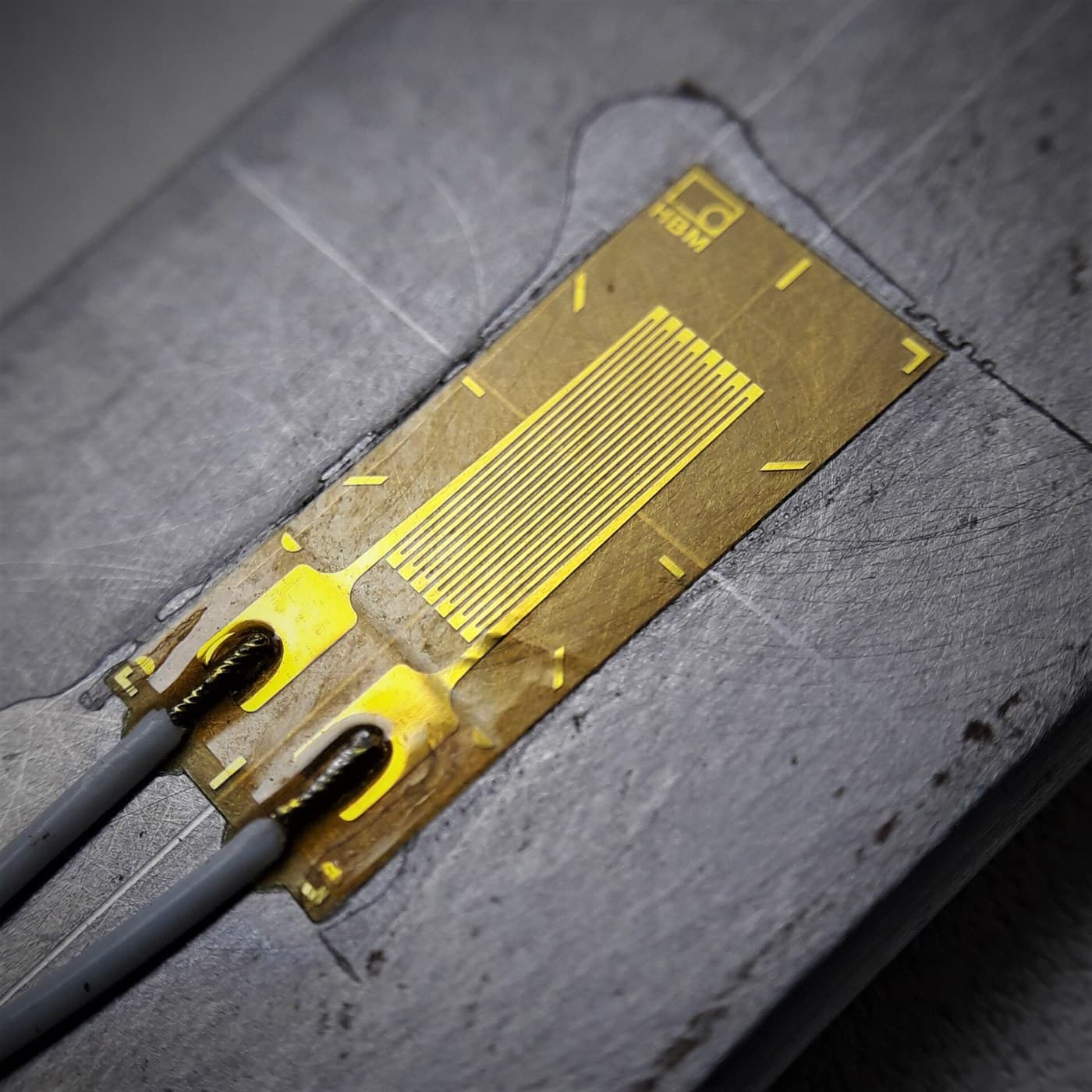
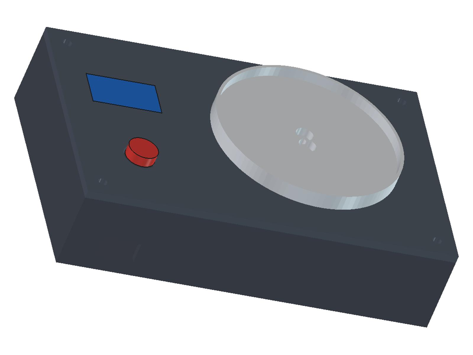
A small precision scale that reads in 0.01 g steps up to 80 g. A 100 g parallel-beam load cell, the shape Eric Laimins patented in 1961, bends a little under the pan; a 24-bit HX711 reads its bridge, an ESP32 averages and shows grams on an OLED. One button tares and calibrates. The case and pan are printed in PETG.
Intermediate
About 1 day, mostly printing

Instructions

1

Watch it built

An ESP32, an HX711 board and a load cell made into a scale with an OLED, including calibration (Electronic Clinic). Ours uses a smaller, finer cell.
2

The load cell: Laimins, 1961

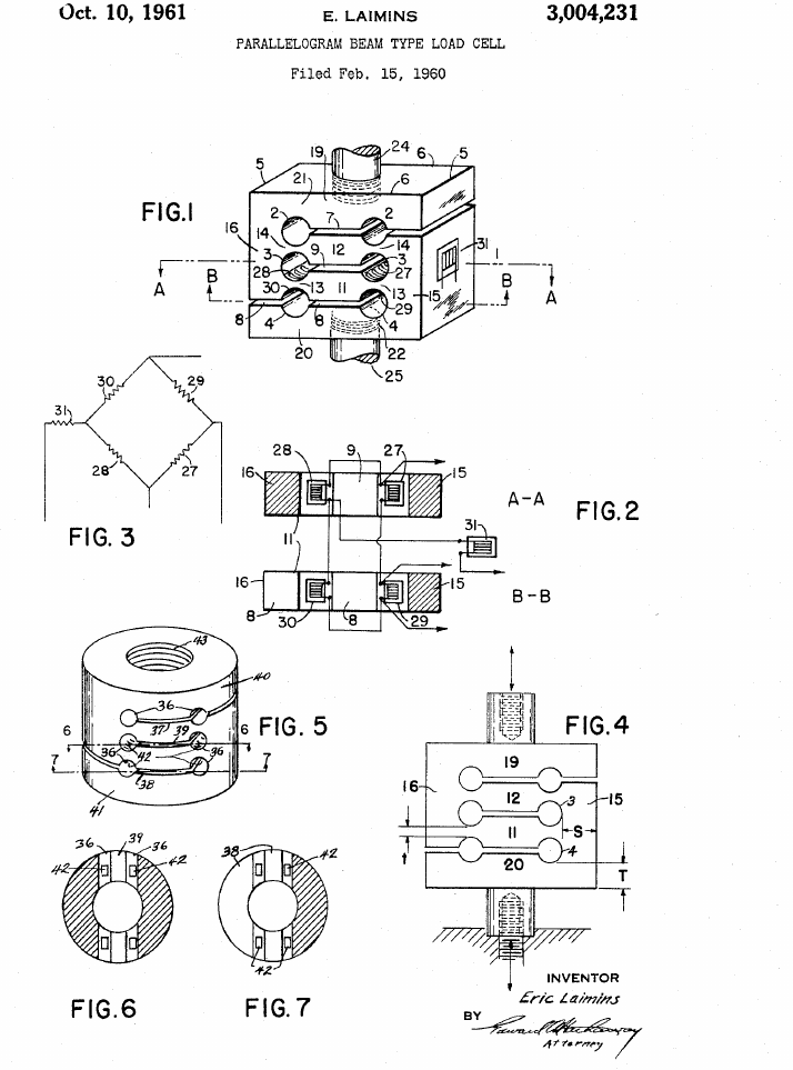
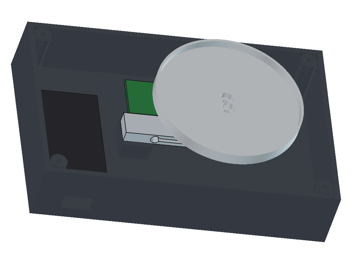
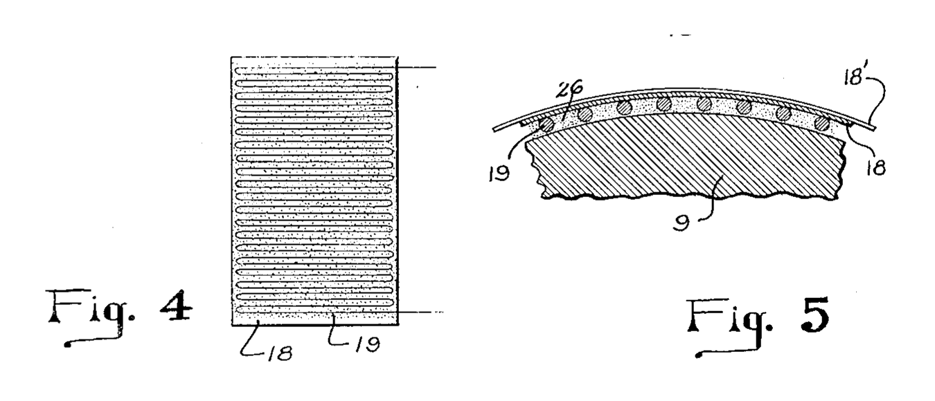
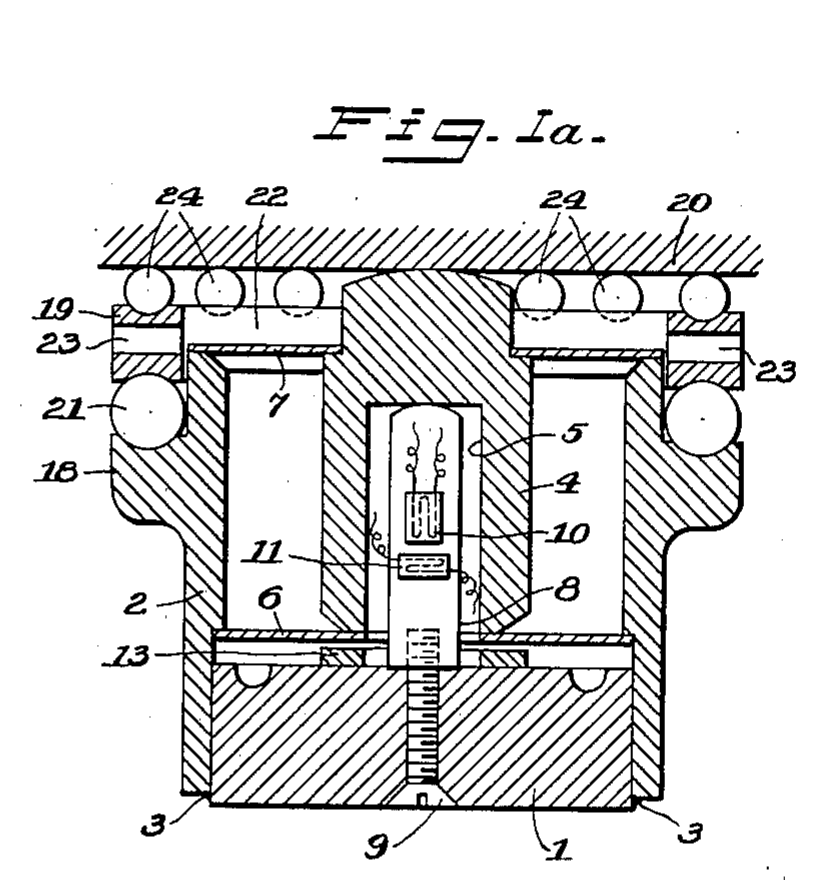
US 3,004,231 (Eric Laimins, 1961): one block with three pairs of cross holes joined by slots makes two parallel beams with thin flexures, so the ends stay parallel under load and the reading hardly depends on where the load sits. Bonded strain gauges on the hole walls form a bridge (his Fig. 3). He found S/t 40:1 and T/t 20:1 gave excellent results. The bar cells sold today have this shape.
Step 2 - Image 1
3

How fine can it read?

Loading Jupyter Notebook...

Tools needed:

MultimeterMultimeter
4

Print the base

Floor down, no supports, PETG, 0.2 mm layers, 3 walls. The boss carries the cell's fixed end; the slot in the front wall is for the USB lead.
Design FileSTLCC0 - Free

Materials for this step:

PETG FilamentPETG Filament95 g

Tools needed:

FDM 3D PrinterFDM 3D Printer
5

Print the lid

Flat, no supports. Windows for the OLED and the 12 mm button, and a hole for the pan's post.
Design FileSTLCC0 - Free

Materials for this step:

PETG FilamentPETG Filament45 g

Tools needed:

FDM 3D PrinterFDM 3D Printer
6

Print the pan

Print it upside down: dish face on the bed, post up. It is the pan, and everything on the cell counts against its 100 g, so do not make it heavier.
Design FileSTLCC0 - Free

Materials for this step:

PETG FilamentPETG Filament15 g

Tools needed:

FDM 3D PrinterFDM 3D Printer
7

Change the case (optional)

The FreeCAD script that made the three parts; change sizes at the top and run: OUT=. freecadcmd build_all.py
build_all.pypython
"""Batch 2524 -- printed case for a 100 g precision scale: a TAL221-type parallel-beam bar load cell (47 x 12 x 6 mm, holes 40 mm
apart, 2 x M3 tapped at one end, 2 x 3.2 mm through at the other, 6 mm apart; HTC-Sensor datasheet), an HX711 board, an ESP32
DevKit and a 0.96 in I2C OLED. ALL sizes ours. Three parts, each printed flat face down, no supports:
  scale-base   tray 140 x 90 x 30 mm, boss under the cell's fixed end (counterbored for 2 x M3 x 14 from below), USB slot,
               4 corner posts with 2.8 mm pilot holes for the lid screws
  scale-lid    3 mm plate: OLED window, 12 mm button hole, clearance hole for the carrier post, 4 x 3.4 mm screw holes
  scale-carrier  70 mm dish (2 mm floor, 6 mm rim) on a 12 x 14 mm post, bolted to the cell's free end (2 x M3 x 30, nuts
               under the cell). It is the pan: everything resting on the cell counts against its 100 g, so it is kept light.
Run: OUT=<dir> freecadcmd build_all.py   (mm, z up; the base floor sits on the bed)."""
import os
import FreeCAD as App, Part, MeshPart
OUT = os.environ["OUT"]
V = App.Vector
L, W, H = 140.0, 90.0, 30.0            # tray outside; walls to z = 30
FLOOR, WALL = 3.0, 2.4
CELL_L, CELL_W, CELL_T = 47.0, 12.0, 6.0
HOLE_INSET, HOLE_PITCH = 3.5, 6.0      # holes 3.5 mm from each end (47 - 40) / 2, 6 mm apart across the bar
CELL_X0, CELL_YC = 45.0, 45.0          # fixed end of the cell at x = 45, cell centred across the tray
BOSS_TOP = 12.0                        # cell underside sits at z = 12
LID_T = 3.0
POST_W, POST_D = 12.0, 14.0            # carrier post along x, y
DISC_D, DISC_T, DISC_GAP = 70.0, 2.0, 3.0
RIM_H, RIM_T = 6.0, 1.2
CB_D, CB_H = 6.5, 3.2                  # counterbore for an M3 socket head (5.5 mm head, 3 mm high)

def save(sh, name):
    sh = sh.removeSplitter()
    bb = sh.BoundBox
    print(name, "valid", sh.isValid(), "solids", len(sh.Solids), "bbox", [round(v, 1) for v in (bb.XLength, bb.YLength, bb.ZLength)],
          "volume_cm3", round(sh.Volume / 1000, 1))
    MeshPart.meshFromShape(Shape=sh, LinearDeflection=0.03, AngularDeflection=0.12).write(os.path.join(OUT, name + ".stl"))
    return sh

fx = CELL_X0 + HOLE_INSET                       # fixed-end hole line
gx = CELL_X0 + CELL_L - HOLE_INSET              # free-end hole line (40 mm on)
ys = (CELL_YC - HOLE_PITCH / 2, CELL_YC + HOLE_PITCH / 2)
cell_top = BOSS_TOP + CELL_T                    # 18
lid_top = H + LID_T                             # 33

# ---- base tray
base = Part.makeBox(L, W, H).cut(Part.makeBox(L - 2 * WALL, W - 2 * WALL, H, V(WALL, WALL, FLOOR)))
boss = Part.makeBox(14.0, 16.0, BOSS_TOP - FLOOR, V(CELL_X0, CELL_YC - 8.0, FLOOR))
base = base.fuse(boss)
for y in ys:
    base = base.cut(Part.makeCylinder(1.7, BOSS_TOP + 1, V(fx, y, -0.5)))          # 3.4 mm clearance
    base = base.cut(Part.makeCylinder(CB_D / 2, CB_H + 0.5, V(fx, y, -0.5)))     # head counterbore from below
POSTS = [(WALL + 4.5, WALL + 4.5), (L - WALL - 4.5, WALL + 4.5), (WALL + 4.5, W - WALL - 4.5), (L - WALL - 4.5, W - WALL - 4.5)]
for (x, y) in POSTS:
    p = Part.makeCylinder(4.0, H - FLOOR, V(x, y, FLOOR)).cut(Part.makeCylinder(1.4, H, V(x, y, FLOOR + 6)))   # 2.8 mm pilot, 21 mm deep
    base = base.fuse(p)
base = base.cut(Part.makeBox(14.0, WALL + 2, 8.0, V(13.0, -1, FLOOR + 3)))        # USB slot in the front wall (ESP32 at the left)
base = save(base, "scale-base")

# ---- lid
lid = Part.makeBox(L, W, LID_T, V(0, 0, H))
lid = lid.cut(Part.makeBox(26.0, 15.0, LID_T + 2, V(11.0, 52.0, H - 1)))          # OLED window (active area 0.96 in, 128 x 64)
lid = lid.cut(Part.makeCylinder(6.1, LID_T + 2, V(24.0, 25.0, H - 1)))           # 12 mm panel push button
lid = lid.cut(Part.makeBox(POST_W + 4, POST_D + 4, LID_T + 2, V(gx - POST_W / 2 - 2, CELL_YC - POST_D / 2 - 2, H - 1)))
for (x, y) in POSTS:
    lid = lid.cut(Part.makeCylinder(1.7, LID_T + 2, V(x, y, H - 1)))
lid = save(lid, "scale-lid")

# ---- pan carrier (modelled in place: post from the cell top to the disc, disc DISC_GAP above the lid)
disc_z = lid_top + DISC_GAP
car = Part.makeBox(POST_W, POST_D, disc_z - cell_top, V(gx - POST_W / 2, CELL_YC - POST_D / 2, cell_top))
car = car.fuse(Part.makeCylinder(DISC_D / 2, DISC_T, V(gx, CELL_YC, disc_z)))
car = car.fuse(Part.makeCylinder(DISC_D / 2, RIM_H, V(gx, CELL_YC, disc_z)).cut(Part.makeCylinder(DISC_D / 2 - RIM_T, RIM_H + 1, V(gx, CELL_YC, disc_z + DISC_T))))
for y in ys:
    car = car.cut(Part.makeCylinder(1.7, disc_z + DISC_T, V(gx, y, cell_top - 1)))
    car = car.cut(Part.makeCylinder(CB_D / 2, CB_H + 0.5, V(gx, y, disc_z + DISC_T - CB_H)))
car = save(car, "scale-carrier")

# checks (our numbers)
print("cell underside z", BOSS_TOP, "top", cell_top, "; free end clears the floor by", BOSS_TOP - FLOOR, "mm")
print("fixed-end screw: from the counterbore seat to the cell top", round(cell_top - CB_H, 1), "mm -> M3 x 14 leaves",
      round(14 - (BOSS_TOP - CB_H), 1), "mm in the 6 mm thread")
grip = disc_z + DISC_T - CB_H - BOSS_TOP
print("carrier screw: seat z", round(disc_z + DISC_T - CB_H, 1), "to cell underside", BOSS_TOP, "=", round(grip, 1),
      "mm -> M3 x 30 leaves", round(30 - grip, 1), "mm below the cell for the 2.4 mm nut")
print("carrier volume", round(car.Volume / 1000, 2), "cm3 -> solid PETG at 1.27 g/cm3:", round(car.Volume / 1000 * 1.27, 1), "g (the most it can weigh)")
print("disc underside", disc_z, "lid top", lid_top, "post clearance in the lid hole 2 mm each side")
print("disc spans x", gx - DISC_D / 2, "to", gx + DISC_D / 2, "(tray 0 to", L, ")")

Tools needed:

Digital Caliper 6-InchDigital Caliper 6-Inch
8

Bolt the pan to the cell

Push the pan's post down through the lid's hole. Under the lid, bolt the post to the cell end with the two 3.2 mm holes: 2 x M3 x 30 socket screws from the pan side, 2 x M3 nuts under the cell. The cell lies flat (load through its mounting holes); its cable leaves the other, M3 end, which goes on the boss.
Step 8 - Image 1

Materials for this step:

Load CellLoad Cell1 piece (100 g bar, parallel beam, 0.6 mV/V)

Socket Head Cap ScrewSocket Head Cap Screw2 piece (M3 x 30)
Hex NutHex Nut2 piece (M3)

Tools needed:

Hex Key SetHex Key Set
9

Wire it

Cell to HX711: red E+, black E-, green A+, white A-. HX711: VCC and GND to the ESP32's 3V3 and GND, DT to GPIO16, SCK to GPIO4. OLED: VCC 3V3, GND, SDA GPIO21, SCL GPIO22. Button: one leg to GPIO27, the other to GND. Solder the cell's fine wires and cover each joint with heat-shrink; keep the cell's wires slack so they do not pull on it.

Materials for this step:

Load Cell AmplifierLoad Cell Amplifier1 piece
ESP32 Development BoardESP32 Development Board1 piece
OLED DisplayOLED Display1 piece (0.96 in, I2C, SSD1306)
Push ButtonPush Button1 piece (12 mm panel, momentary)

Jumper WiresJumper Wires12 pieces
Hookup WireHookup Wire0.5 m
Solder WireSolder Wire2 g
Heat Shrink TubingHeat Shrink Tubing8 cm

Tools needed:

Soldering IronSoldering Iron
Wire StrippersWire Strippers
10

Load the firmware

Install Adafruit SSD1306 and Adafruit GFX from the Library Manager, choose ESP32 Dev Module, upload. Short press = tare; hold 3 s = calibrate.
precision_scale.inocpp
// Precision scale, 100 g by 0.01 g: HX711 + parallel-beam bar load cell + ESP32 + 0.96 in SSD1306 OLED (I2C, address 0x3C).
// CC0. Pins (ours): HX711 DT -> GPIO16, SCK -> GPIO4; OLED SDA -> GPIO21, SCL -> GPIO22; button GPIO27 to GND.
// The HX711 is read as its datasheet says: wait for DOUT low, 25 clock pulses (24 data bits MSB first, the 25th selects
// channel A, gain 128 for the next reading), 24-bit two's complement. A clock pulse held high for over 60 us powers the
// chip down, so the pulses run with interrupts off.
// Weighs up to 80 g: the cell carries 100 g, and the printed pan, its screws and nuts rest on it all the time.
// Short press: tare. Press and hold 3 s with the pan empty, then put the 50.00 g weight on when asked: calibration.
// Libraries: Adafruit SSD1306 and Adafruit GFX (Arduino Library Manager). Board: ESP32 Dev Module.
#include <Wire.h>
#include <Adafruit_GFX.h>
#include <Adafruit_SSD1306.h>
#include <Preferences.h>

const int PIN_DT = 16, PIN_SCK = 4, PIN_BTN = 27;
const float CAL_MASS_G = 50.00;   // the calibration weight you use
const int N_AVG = 8;              // readings averaged (10 per second at RATE = 0)

Adafruit_SSD1306 oled(128, 64, &Wire, -1);
Preferences prefs;
portMUX_TYPE mux = portMUX_INITIALIZER_UNLOCKED;
long tareRaw = 0;
float countsPerGram = 0;          // set by calibration, kept in flash

long readRaw() {
  while (digitalRead(PIN_DT) == HIGH) delay(1);       // DOUT low = data ready
  long v = 0;
  portENTER_CRITICAL(&mux);
  for (int i = 0; i < 24; i++) {
    digitalWrite(PIN_SCK, HIGH); delayMicroseconds(1);
    v = (v << 1) | digitalRead(PIN_DT);
    digitalWrite(PIN_SCK, LOW); delayMicroseconds(1);
  }
  digitalWrite(PIN_SCK, HIGH); delayMicroseconds(1);   // 25th pulse: channel A, gain 128
  digitalWrite(PIN_SCK, LOW); delayMicroseconds(1);
  portEXIT_CRITICAL(&mux);
  if (v & 0x800000) v |= 0xFF000000;                   // sign-extend the 24-bit two's complement
  return v;
}

long readAvg(int n) {
  long long s = 0;
  for (int i = 0; i < n; i++) s += readRaw();
  return (long)(s / n);
}

void show(const char* top, const char* big) {
  oled.clearDisplay();
  oled.setTextColor(SSD1306_WHITE);
  oled.setTextSize(1); oled.setCursor(0, 0); oled.print(top);
  oled.setTextSize(2); oled.setCursor(0, 28); oled.print(big);
  oled.display();
}

void calibrate() {
  show("Calibrate: pan empty", "wait...");
  delay(1500);
  long empty = readAvg(32);
  char msg[24]; snprintf(msg, sizeof msg, "%.2f g", CAL_MASS_G);
  show("Put on the weight:", msg);
  while (digitalRead(PIN_BTN) == HIGH) delay(10);      // press when the weight is on and still
  delay(1500);
  long loaded = readAvg(32);
  countsPerGram = (loaded - empty) / CAL_MASS_G;
  prefs.putFloat("cpg", countsPerGram);
  tareRaw = empty;
  show("Saved. Remove weight", "done");
  delay(2000);
}

void setup() {
  pinMode(PIN_SCK, OUTPUT); digitalWrite(PIN_SCK, LOW);   // low = HX711 running
  pinMode(PIN_DT, INPUT);
  pinMode(PIN_BTN, INPUT_PULLUP);
  Wire.begin(21, 22);
  oled.begin(SSD1306_SWITCHCAPVCC, 0x3C);
  prefs.begin("scale", false);
  countsPerGram = prefs.getFloat("cpg", 0);
  delay(500);                                             // datasheet settling time 400 ms at 10 SPS
  tareRaw = readAvg(16);
  if (countsPerGram == 0) calibrate();
}

void loop() {
  if (digitalRead(PIN_BTN) == LOW) {
    unsigned long t0 = millis();
    while (digitalRead(PIN_BTN) == LOW && millis() - t0 < 3000) delay(10);
    if (millis() - t0 >= 3000) { while (digitalRead(PIN_BTN) == LOW) delay(10); calibrate(); }
    else { show("Tare", "..."); tareRaw = readAvg(16); }
  }
  float g = (readAvg(N_AVG) - tareRaw) / countsPerGram;
  if (fabs(g) < 0.005) g = 0;                             // no "-0.00"
  char big[16]; snprintf(big, sizeof big, "%7.2f g", g);
  show(g > 80.0 ? "OVER 80 g - unload" : "Precision scale", big);
}

Materials for this step:

USB-C CableUSB-C Cable1 piece

Tools needed:

Computer with Arduino IDEComputer with Arduino IDE
11

Close the case

Stick the ESP32 (USB to the front slot) and the HX711 to the floor with double-sided tape, the OLED behind its window, the button through its hole. Lower lid, cell and pan onto the base so the cell's tapped end sits on the boss; from underneath, 2 x M3 x 14 into the cell's M3 holes. Lid: 4 x M3 x 10 into the corner posts. The pan must not touch the lid anywhere.

Materials for this step:

Socket Head Cap ScrewSocket Head Cap Screw6 piece (2 x M3 x 14, 4 x M3 x 10)

Double-Sided TapeDouble-Sided Tape0.2 m

Tools needed:

Hex Key SetHex Key Set

Craft KnifeCraft Knife
12

Calibrate and check

Stand it level on a steady table out of draughts and let it warm up 10 minutes. Empty pan: short press to tare. Hold the button 3 s, put the 50 g weight on when asked, press again. Check 10 g, 20 g and 50 g, and put the 50 g on and off five times: the readings should agree within about 0.05 g.

Tools needed:

Calibration Weight SetCalibration Weight Set
Spirit LevelSpirit Level
13

Troubleshooting

Scale problems and fixes.

Flow

Loading...
14

History and honest limits

Eric Laimins, Cambridge, Mass., assignor to Baldwin-Lima-Hamilton Corporation: US 3,004,231, "Parallelogram Beam Type Load Cell", filed 15 Feb 1960, granted 10 Oct 1961. His block floats on two load rods instead of being clamped, so clamping does not strain the gauges. Ours: the bought cell, the case, the pins, the firmware and every size. The display shows 0.01 g, but the cell's datasheet allows about +/- 0.05 g (repeatability, hysteresis, creep); weigh up to 80 g. Not built or tested by us yet.

Materials

14

Tools Required

10

Design Files

3

Related Blueprints

These blueprints share knowledge with this one — techniques, materials, or principles that connect them in the learning graph.
CC0 Public Domain

This blueprint is released under CC0. You are free to copy, modify, distribute, and use this work for any purpose, without asking permission.

Support the Maker by purchasing products through their Blueprint where they earn a Maker Commission set by Vendors, or create a new iteration of this Blueprint and include it as a connection in your own Blueprint to share revenue.

Discussion

(0)

Log in to join the discussion

Loading comments...