Collaboration
ART
BEAUTY & WELLNESS
CRAFT
CULTURE & HISTORY
ENTERTAINMENT
ENVIRONMENT
FOOD & DRINKS
REVERSE ENGINEERING
SCIENCES
SPORTS
TECHNOLOGY
WEARABLES
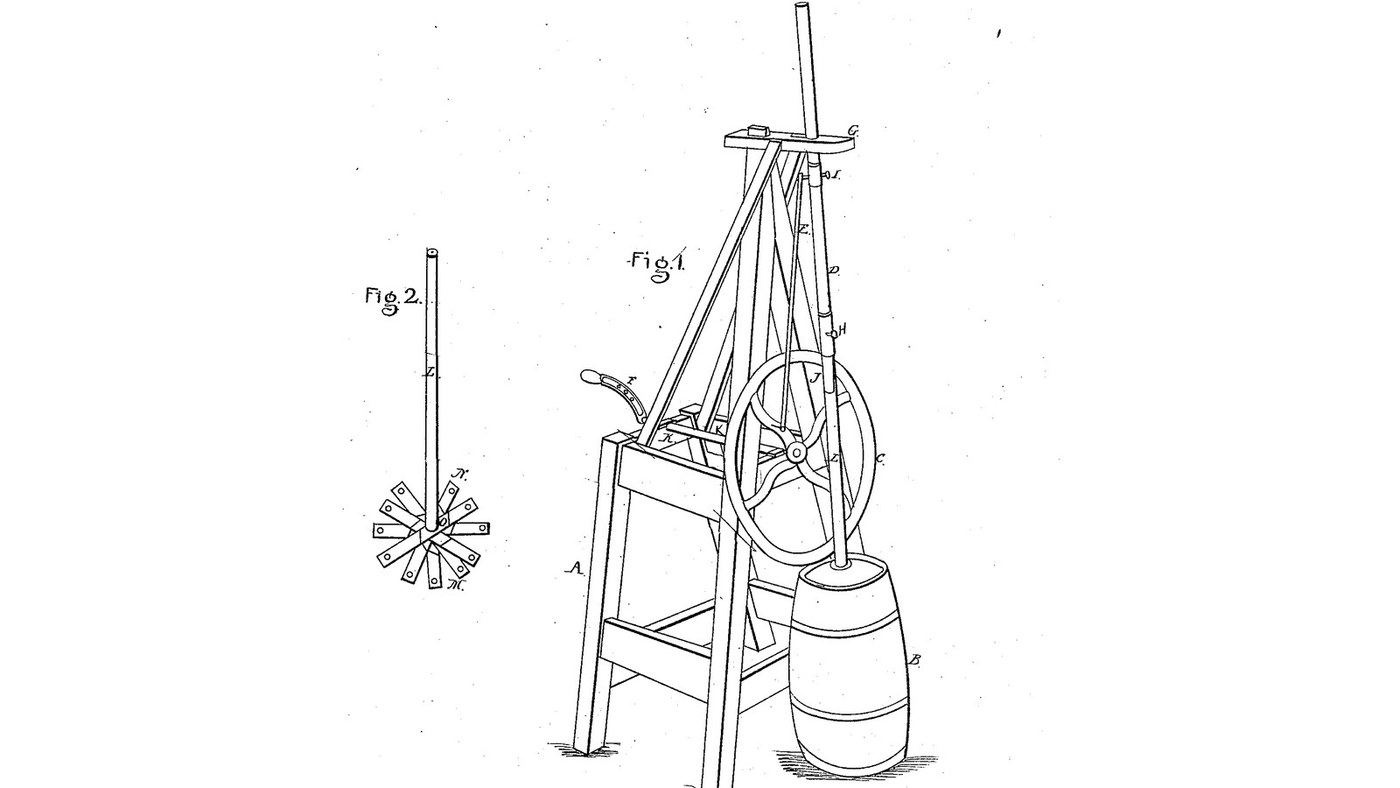

Balance-Wheel Churn Frame: A Weighted Wheel Drives the Dash Up and Down and Its Pitched Blades Make It Revolve
Nathan D. Ross of Braintrim, Pennsylvania, received US 28,607, dated 5 June 1860, for a churn. A tall timber frame carries a shaft with a heavy balance wheel at one end and a crank at the other; a rod from an adjustable wrist on the wheel drives the dash staff up and down through a guide. The staff joins the churn handle by a swivel, and the dashers' blades all stand at one angle, so the dash turns right and left as it is driven through the cream.
The frame's, shaft's, wheel's and dasher pieces' sizes are the patent's own, given as "about"; all others are ours.
Advanced
About 3 days
Instructions
1
1
The patent's sizes, and a wheel of about 30 pounds
The patent's sizes, and a wheel of about 30 pounds
Loading Jupyter Notebook...
2
2
A crank frame over an ordinary churn, one week before
A crank frame over an ordinary churn, one week before
Evans gears his crank up. Ross gives his a heavy balance wheel and an adjustable stroke.
3
3
Read US 28,607
Read US 28,607
"The nature of my invention consists in lengthening or shortening the stroke and lowering and raising the dash so as to give it the right position in the churn at the same time giving the dash an independent revolving motion to the right and left and giving the operator power over the work to be done."
4
4
Frame A, cap G and braces
Frame A, cap G and braces
From 51 mm square timber (the patent's two inches) cut two front posts about 1.83 m long and two back posts about 0.91 m. Set the feet about 0.91 m apart; lean the front posts in so they meet at the top, and the back posts at the same angle. Join front and back posts on each side with two side cross pieces about 0.81 m between shoulders, at 300 and 860 mm up, and front and back with cross pieces at the same heights, cut to the bevel. On the top of the long posts fix a cap G reaching 410 mm forward, bored 32 mm near its end for the staff, and brace it with two timbers down to near the tops of the short posts.
Materials for this step:
 Pine Lumber6 pieces
 Wood Glue1 piece
 Wood Screws40 pieces
 Carriage Bolt8 pieces
 Nylon Insert Lock Nut8 pieces
Tools needed:
 Table Saw
 Chisel Set - Wood
 Protractor
 Cordless Drill
 Drill Bit Set
 Spade Bit Set
 Bar Clamp
 Adjustable Spanner
 Tape Measure
5
5
Shaft K, balance wheel C and slide crank F
Shaft K, balance wheel C and slide crank F
Bolt a hardwood bearing block bored 26 mm to the middle of each top front and back cross piece, and pass a 25 mm mild steel shaft K through them (the patent's about one inch). Glue two 18 mm plywood discs into a wheel 600 mm across with a rim 50 mm wide and four arms, and screw a ring of 60 x 12 mm mild steel flat bar round it so it weighs about 14 kg, near the patent's 30 pounds. Cut a slot 13 mm wide from 60 to 140 mm out along one arm for the wrist, a 16 mm bolt with a nut. Fix the wheel on the shaft's front end. On the back end fix a crank F of flat bar with three holes for the handle, so it can be lengthened or shortened.
Materials for this step:
 Hardwood Board1 piece
 Mild Steel Round Bar1 piece
 Plywood Sheet1 pieceWood Glue1 piece
 Mild Steel Flat Bar2 piecesWood Screws24 piecesCarriage Bolt4 piecesNylon Insert Lock Nut4 pieces
 Shaft Collar2 pieces
 Hardwood Dowels1 piece
Tools needed:
 JigsawBar ClampCordless DrillDrill Bit Set
 Hacksaw
 Bench Vise
 Files (Hand File)Adjustable Spanner
6
6
Rod E, staff D, socket I, socket H and swivel J
Rod E, staff D, socket I, socket H and swivel J
Cut a 32 mm hardwood staff D about 1.25 m long and pass it up through the cap. Make a hardwood socket I to slide on it, with a lug for the rod and a thumb screw (threaded rod, nut and wing nut) to fix it. Cut a hardwood rod E 730 mm between holes, from the wrist to the lug. Fit a hardwood socket H on the staff's foot, bored 16.5 mm, with a thumb screw through its side; turn the top of the churn handle L down to a 16 mm pin with a groove, so the thumb screw rides in the groove and the handle turns freely: the swivel J.
Materials for this step:
Hardwood Dowels2 piecesHardwood Board1 piece Threaded Rod1 piece
 Hex Nut2 pieces
 Wing Nut2 piecesCarriage Bolt2 piecesNylon Insert Lock Nut2 piecesWood Glue1 piece
Tools needed:
Table SawCordless DrillDrill Bit SetSpade Bit SetHacksawFiles (Hand File)Adjustable Spanner7
7
Handle L and dashers M
Handle L and dashers M
Cut a 28 mm hardwood handle 420 mm long. For each dasher halve together two hardwood pieces 38 x 19 mm (the patent's 1 1/2 x 3/4 inch), 260 long, at right angles, and plane each blade on both sides down to about 6 mm at its edges, every blade bevelled the same way so they all stand on one angle, about 30 degrees. Fix two such dashers on the handle's foot, 60 mm apart.
Materials for this step:
Hardwood Dowels1 pieceHardwood Board1 pieceWood Glue1 piece Stainless Steel Rod1 piece
 Split Pin2 pieces
Tools needed:
Table SawChisel Set - Wood Hand PlaneProtractorCordless DrillDrill Bit Set
8
8
The build in 3D
The build in 3D
FreeCAD model of this build: the frame with its leaning posts, cap G and braces, the shaft K on its bearings with the balance wheel and slide crank, the rod E from the wrist to the socket I on the staff, the swivel and handle with two pitched dashers in the bucket, cut open.
9
9
Churn
Churn
Pour about 10 litres of heavy cream at about 15 °C, checked with the thermometer, into the bucket, stand it under the staff with the handle through its lid, and join handle and staff at the swivel. Set the socket I on the staff so the dash just clears the bottom at the low point, and the wrist for the stroke you want. Turn the crank F, timing it; the wheel carries the stroke round and the dash turns as it goes. When the butter comes, loosen the swivel's thumb screw, lift the handle out, take out the butter, pour the buttermilk into a bowl, wash the butter in cold water until it runs clear, salt and weigh it.
Materials for this step:
 Heavy Cream10 l
 Coarse Sea Salt1 piece
 Water1 piece
 20-Liter Bucket1 piece
Tools needed:
 Leave-In Probe Thermometer
 Stopwatch
 Digital Kitchen Scale
 Stainless Steel Mixing Bowl (Large)
10
10
Troubleshooting
Troubleshooting
Balance-wheel churn troubleshooting.
Flow
Loading...
11
11
History and honest limits
History and honest limits
**Nathan D. Ross** of Braintrim, Wyoming County, Pennsylvania, US 28,607, 5 June 1860, "Churn". He did not claim the up-and-down motion of dasher and handle, but the revolving of the dashers and handle by the series of dashers and blades. The frame, shaft, wheel and dasher-piece sizes are his, given as "about"; he gives the wheel's size and weight but not its material; ours is plywood with a steel ring; the bucket, stroke, rod and blade angle are ours.
Materials
20- 6 piecesPlaceholder
- 4 piecesPlaceholder
- 64 piecesPlaceholder
- 14 piecesPlaceholder
- 14 piecesPlaceholder
- 1 piecePlaceholder
- 1 piecePlaceholder
- 1 piecePlaceholder
- 2 piecesPlaceholder
- 2 piecesPlaceholder
- 2 piecesPlaceholder
- 1 piecePlaceholder
- 2 piecesPlaceholder
- 2 piecesPlaceholder
- 1 piecePlaceholder
- 2 piecesPlaceholder
- 10 lPlaceholder
- 1 piecePlaceholder
- 1 piecePlaceholder
- 1 piecePlaceholder
Tools Required
18- 1 vendor sell this, none ship to you yetPlaceholder
- Placeholder
- Placeholder
- 1 vendor sell this, none ship to you yetPlaceholder
- Placeholder
- Placeholder
- Placeholder
- Placeholder
- 1 vendor sell this, none ship to you yetPlaceholder
- 1 vendor sell this, none ship to you yetPlaceholder
- Placeholder
- Placeholder
- Placeholder
- Placeholder
- Placeholder
- Placeholder
- Placeholder
- Placeholder
Design Files
1This blueprint makes


Related Blueprints
These blueprints share knowledge with this one — techniques, materials, or principles that connect them in the learning graph.
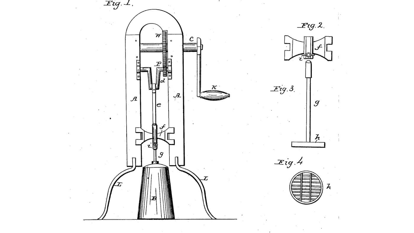
Geared Crank-Frame Churn: A Frame Over an Ordinary Churn Gears a Hand Crank Up to Drive a Grated Dasher by Pitman
by Buttercup
Woodworking
0
0
0
0
0
0
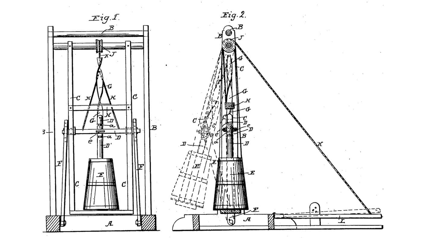
Pendulum Churn: A Treadle Swings the Hung Churn, Arms From the Base Plunge the Dasher and a Twisted Strip Turns It
by Buttercup
Woodworking
0
0
0
0
0
0

Churning Butter from Cream — The 5,000-Year-Old Fat Separation
by TheChef
CRAFT
60
0
0
0
0
0
CC0 Public Domain
This blueprint is released under CC0. You are free to copy, modify, distribute, and use this work for any purpose, without asking permission.
Support the Maker by purchasing products through their Blueprint where they earn a Maker Commission set by Vendors, or create a new iteration of this Blueprint and include it as a connection in your own Blueprint to share revenue.