ART
BEAUTY & WELLNESS
CRAFT
CULTURE & HISTORY
ENTERTAINMENT
ENVIRONMENT
FOOD & DRINKS
REVERSE ENGINEERING
SCIENCES
SPORTS
TECHNOLOGY
WEARABLES
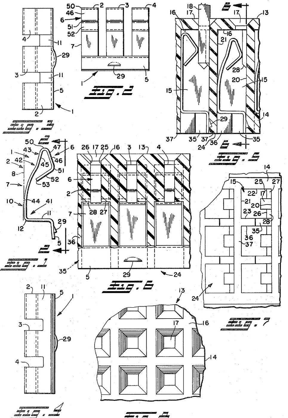


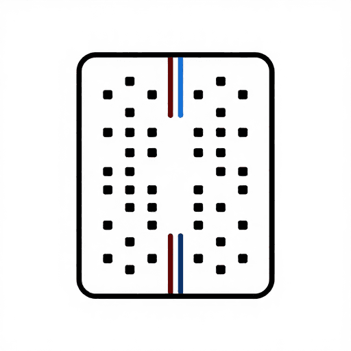
Solderless Breadboard: Cantilever Contacts in a Moulded Acetal Housing (Tengler, US 4,420,215)
A breadboard lets you build a circuit without solder: push component leads into holes and spring contacts underneath join them in rows. John N. Tengler of A P Products received US 4,420,215 (1983) for one: a one-piece moulded acetal housing with holes on 0.100 in centres, and sets of three springy cantilever contacts of copper alloy No. 688 pushed in from below.
Not given: the contact thickness and sizes, how the contacts are formed, and the moulding conditions.
Source: J. N. Tengler, US 4,420,215. Picture: the patent's drawing sheet.
Advanced
Not given in the source
Instructions
1
1
Mould the housing
Mould the housing
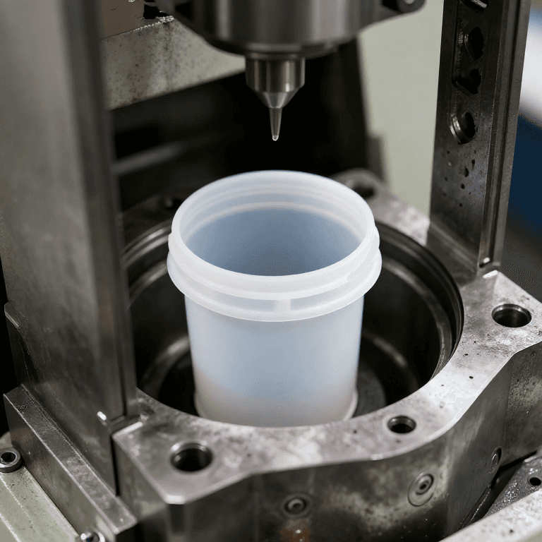
Injection-mould the housing as one piece in acetal copolymer (Tengler names CELCON). His example has 78 cells in 26 rows of three, open at the bottom, under a top wall whose holes sit on 0.100 in centres. Give each cell two preload bars on its front wall, one either side of the hole, with tapered lower ends. Mould notches into the walls between the cells of a row, and none into the front and back walls, so a contact set fits only the right way round.
Materials for this step:
 Acetal Copolymer Pellets1 one housing
Tools needed:
 Injection Moulding Machine
 Injection Mold Frame
 Unknown Dimensions
2
2
Form the contact sets
Form the contact sets
Form three identical contacts from copper alloy No. 688, joined at the foot by a strip. Each is a single cantilever: a foot with a seat, an arm curving up into a spring, a hairpin bend, then a contact face that a pushed-in lead slides along, ending in a tip, with a stop extension that comes to rest against the arm. If you like, stamp a small barb in the joining strip.
Materials for this step:
 Copper Alloy 688 Strip1 one set of three per row
Tools needed:
 Unknown Forming MethodUnknown Dimensions
3
3
Push the sets in from below
Push the sets in from below
Push each set up into its row from the open bottom, contact faces toward the holes, with the strip running through the notches. The strip is bent at a slight angle, so the front wall springs it and wedges the contact's foot against the back wall. The preload bars press on the contact face, and the barb, if there is one, bites into the plastic.
Tools needed:
 Flat-Nose Pliers
4
4
Check a row
Check a row
Push a resistor lead through a hole: it should slide along the contact face. The two end contacts of a row join two components; Tengler meant the middle one for injecting or testing a signal. Check with a meter that the three holes of a row connect and neighbouring rows do not.
Tools needed:
 Resistor
 Multimeter
Materials
2- 1 one housingPlaceholder
- 1 one set of three per rowPlaceholder
Tools Required
7- Placeholder
- Placeholder
- Placeholder
- Placeholder
- Placeholder
- Placeholder
- Placeholder
Connected Blueprint Materials

This blueprint makes
CC0 Public Domain
This blueprint is released under CC0. You are free to copy, modify, distribute, and use this work for any purpose, without asking permission.
Support the Maker by purchasing products through their Blueprint where they earn a Maker Commission set by Vendors, or create a new iteration of this Blueprint and include it as a connection in your own Blueprint to share revenue.