Collaboration
ART
BEAUTY & WELLNESS
CRAFT
CULTURE & HISTORY
ENTERTAINMENT
ENVIRONMENT
FOOD & DRINKS
REVERSE ENGINEERING
SCIENCES
SPORTS
TECHNOLOGY
WEARABLES
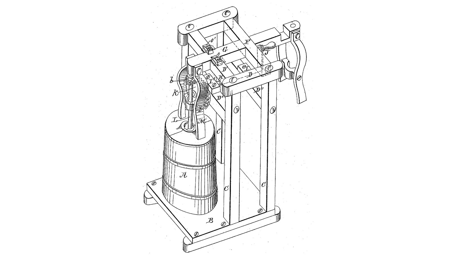

Hinged-Arm Frame Churn: An Arm That Swings Back Holds the Dasher's Top, Its Forked Brace Holds the Cover Down
John Stilwell of Griffin, Georgia, received US 32,388, dated 21 May 1861, for a stand that turns the dasher of an upright churn. The churn stands on a base in front of a frame; an arm fixed to a cross bar turning in the frame's top reaches over it and holds the dasher's top, while a crank shaft on the frame turns the dasher through bevel gearing. A forked brace hinged to the arm presses the two half covers and the churn down. Turn the brace up to look in, or loosen two buttons and swing the arm back to take the churn out.
The patent gives no sizes; every size here is ours.
Intermediate
About 3 days
Instructions
1
1
Swinging the arm clear
Swinging the arm clear
Loading Jupyter Notebook...
2
2
A hinged bearing over the churn, a year before
A hinged bearing over the churn, a year before
Mitchell hangs the dasher from a hinged journal box. Stilwell steps it in the churn and holds its top in an arm that swings back.
3
3
Read US 32,388
Read US 32,388
"By means of the forked brace bar the churn is held in position in the frame without other fastening and the cover firmly fastened thereon, thus preventing the cream from being thrown out by the action of the beaters. The brace bar also serves to steady the end of the arm in which the beater shaft is stepped."
4
4
Base B, uprights C and cross ties D, D', D''
Base B, uprights C and cross ties D, D', D''
Glue up a hardwood base B 400 x 600 x 30 mm. Mortise four hardwood uprights C 40 x 40 mm, 603 long, into it at the back, 220 mm apart side to side, in pairs 100 mm apart front to back, 230 mm behind where the churn's centre will be. Join each side pair at the top with a cross tie D 40 x 30, 160 long, bored 20.6 mm across 40 mm from its front end for the cross bar's journals; join the front pair with a cross tie D' 260 long, 30 below the top; and join each pair 430 mm up with a cross tie D'' 260 x 40 x 20 for the crank shaft's boxes.
Materials for this step:
 Hardwood Board4 pieces
 Wood Glue1 piece
 Wood Screws24 pieces
Tools needed:
 Table Saw
 Chisel Set - Wood
 Router
 Cordless Drill
 Drill Bit Set
 Spade Bit Set
 Bar Clamp
 Tape Measure
5
5
Cross bar F, arm G, buttons O, O' and brace bar M
Cross bar F, arm G, buttons O, O' and brace bar M
Run a 20 mm stainless rod 270 mm long as the cross bar F through both cross ties D. Cut a hardwood arm G 40 x 30 mm, 310 long, bore it across 20.4 mm 20 mm from its back end, and pin it on F so it reaches forward over the churn's centre resting on the tie D'. Glue a hardwood block 40 x 40 x 40 under its front end, bored 16.6 mm 30 deep from below for the staff's top. Screw two hardwood buttons O, O' on the tie D' either side of the arm, to turn over it. For the brace bar M, cut two hardwood legs 20 x 20 mm, 250 long, and a foot bar 110 x 20 x 12 notched for the staff, and hang the legs either side of the arm on a 12 mm stainless pin through it above the staff, so the foot presses the cover.
Materials for this step:
 Stainless Steel Rod2 piecesHardwood Board1 pieceWood Glue1 pieceWood Screws6 pieces
 Split Pin4 pieces
Tools needed:
Table SawCordless DrillDrill Bit SetSpade Bit Set Hacksaw
 Files (Hand File)
 Screwdriver Set
6
6
Print the step
Print the step
The step in the churn's bottom: 40 mm across, 12 high, with a 16.8 mm hole 8 deep. PETG, 0.2 mm layers, 30 % infill, 4 walls.
7
7
Print the pinion b
Print the pinion b
The pinion on the staff: 14 teeth, module 2.5, 16.2 mm bore. PETG, 0.2 mm layers, 30 % infill, 4 walls.
8
8
Print the bevel wheel K
Print the bevel wheel K
The driving wheel K: a crown wheel of 42 teeth, module 2.5, 16.2 mm bore. PETG, 0.2 mm layers, 30 % infill, 4 walls.
9
9
Churn A, covers, staff L, shaft H, wheel K and crank J
Churn A, covers, staff L, shaft H, wheel K and crank J
Use a 20-litre food-grade bucket as the churn A on the base in front of the frame, with the step in its bottom. Cut a 12 mm HDPE cover to it and saw it in two halves through a 17 mm centre hole. Cut a 16 mm stainless staff L 586 mm long, screw two crossed hardwood slats 240 x 30 x 8 mm on hubs 70 and 170 mm above its foot as the dasher, and pin the pinion b on it 420 mm above the churn's floor. Screw two hardwood boxes I, I' 50 x 24 x 47 mm on the D'' ties, bored 16.6 mm across 23 mm above them. Run a 16 mm stainless shaft H 410 mm long through them with the wheel K pinned on its front end meshing b, a shaft collar behind the front box, and a crank J of mild steel flat bar, 100 mm throw, with a hardwood handle at the back.
Materials for this step:
 20-Liter Bucket1 piece
 HDPE Sheet1 pieceStainless Steel Rod2 piecesHardwood Board1 piece
 Hardwood Dowels1 pieceWood Screws8 pieces
 Shaft Collar1 pieceSplit Pin3 pieces
 Mild Steel Flat Bar1 piece
 PETG Filament1 piece
Tools needed:
 FDM 3D Printer
 Compass
 JigsawSpade Bit SetCordless DrillDrill Bit SetHacksawFiles (Hand File)
 Bench ViseScrewdriver Set
10
10
The build in 3D
The build in 3D
FreeCAD model of this build, the churn cut open: the base and frame, the cross bar with the arm and its bearing block, the buttons, the forked brace bar on the covers, the staff with its slats and pinion, and the crank shaft with the bevel wheel running back through the frame to the crank.
11
11
Churn
Churn
With the arm turned back, stand the churn on the base with the staff in its step, pour in about 10 litres of heavy cream at about 15 °C, checked with the thermometer, and lay on the half covers. Swing the arm down over the staff's top, turn the buttons over it and let the brace bar rest on the covers. Turn the crank steadily, timing it. To look in, turn the brace up and lift a half cover. When the butter comes, turn the buttons, swing the arm back, lift out the staff, take out the butter, pour the buttermilk into a bowl, wash the butter in cold water until it runs clear, salt and weigh it.
Materials for this step:
 Heavy Cream10 l
 Coarse Sea Salt1 piece
 Water1 piece
Tools needed:
 Leave-In Probe Thermometer
 Stopwatch
 Digital Kitchen Scale
 Stainless Steel Mixing Bowl (Large)
12
12
Troubleshooting
Troubleshooting
Hinged-arm churn troubleshooting.
Flow
Loading...
13
13
History and honest limits
History and honest limits
**John Stilwell** of Griffin, Spalding County, Georgia, US 32,388, 21 May 1861, "Churn". He claimed "the combination of the brace bar M, hinged arm G, buttons O, O', with a vertical barrel churn and rotary dasher shaft L". He neither drew nor described the dasher on the shaft; ours is two crossed slats. His churn was a hooped barrel and his gears bevel wheels; ours are a bucket and a printed crown wheel and pinion. The patent gives no sizes; every size here is ours.
Materials
14- 4 piecesPlaceholder
- 2 piecesPlaceholder
- 38 piecesPlaceholder
- 2 piecesPlaceholder
- 7 piecesPlaceholder
- 1 piecePlaceholder
- 1 piecePlaceholder
- 1 piecePlaceholder
- 1 piecePlaceholder
- 1 piecePlaceholder
- 1 piecePlaceholder
- 10 lPlaceholder
- 1 piecePlaceholder
- 1 piecePlaceholder
Tools Required
19- 1 vendor sell this, none ship to you yetPlaceholder
- Placeholder
- Placeholder
- 1 vendor sell this, none ship to you yetPlaceholder
- Placeholder
- Placeholder
- Placeholder
- 1 vendor sell this, none ship to you yetPlaceholder
- Placeholder
- Placeholder
- Placeholder
- Placeholder
- Placeholder
- 1 vendor sell this, none ship to you yetPlaceholder
- Placeholder
- Placeholder
- Placeholder
- Placeholder
- Placeholder
Design Files
4This blueprint makes


Related Blueprints
These blueprints share knowledge with this one — techniques, materials, or principles that connect them in the learning graph.
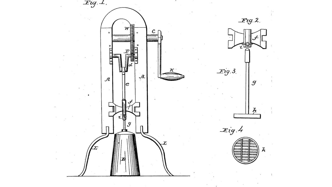
Geared Crank-Frame Churn: A Frame Over an Ordinary Churn Gears a Hand Crank Up to Drive a Grated Dasher by Pitman
by Buttercup
Woodworking
1
0
0
0
0
0
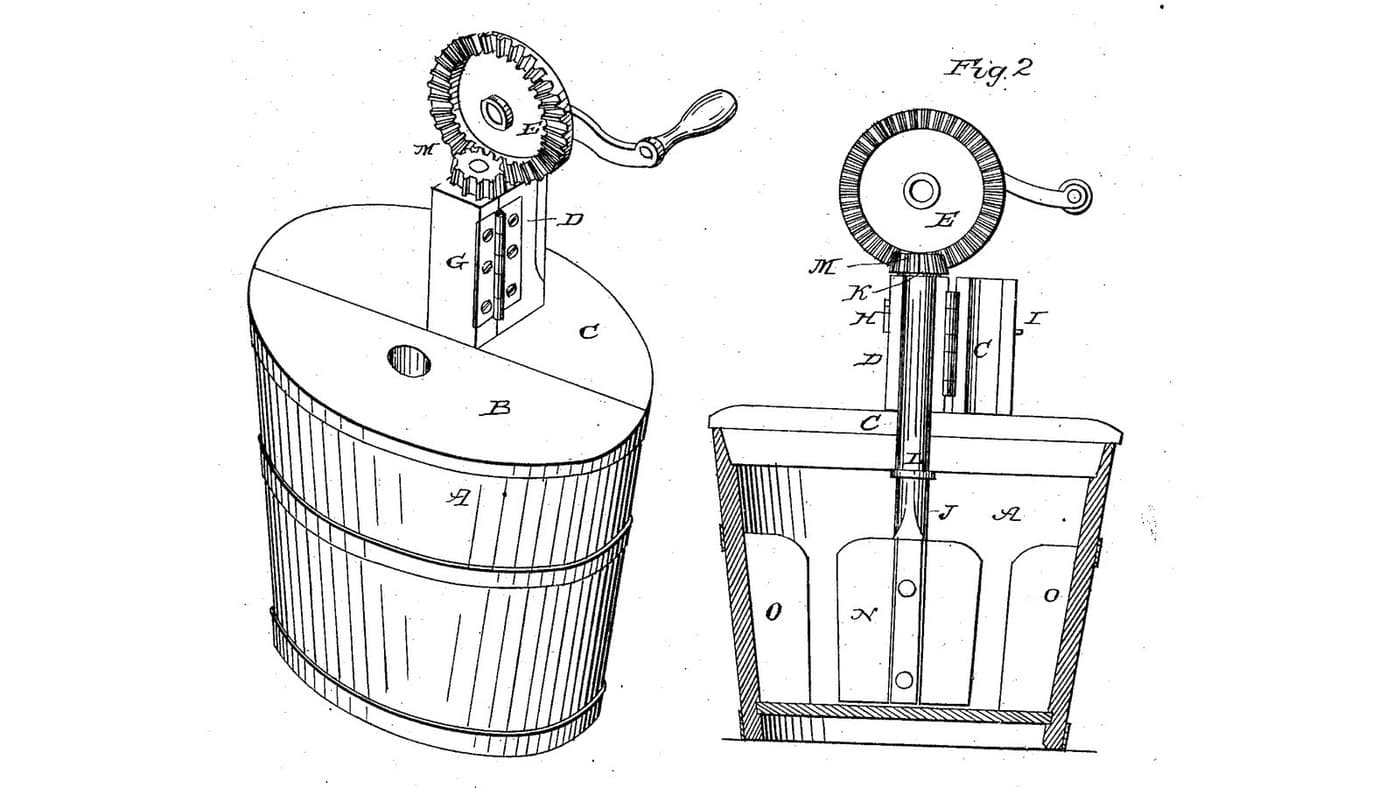
Hung-Dasher Churn: The Dasher Hangs in a Long Hinged Journal Box Above the Lid, No Step in the Tub
by Buttercup
Woodworking
0
0
0
0
0
0
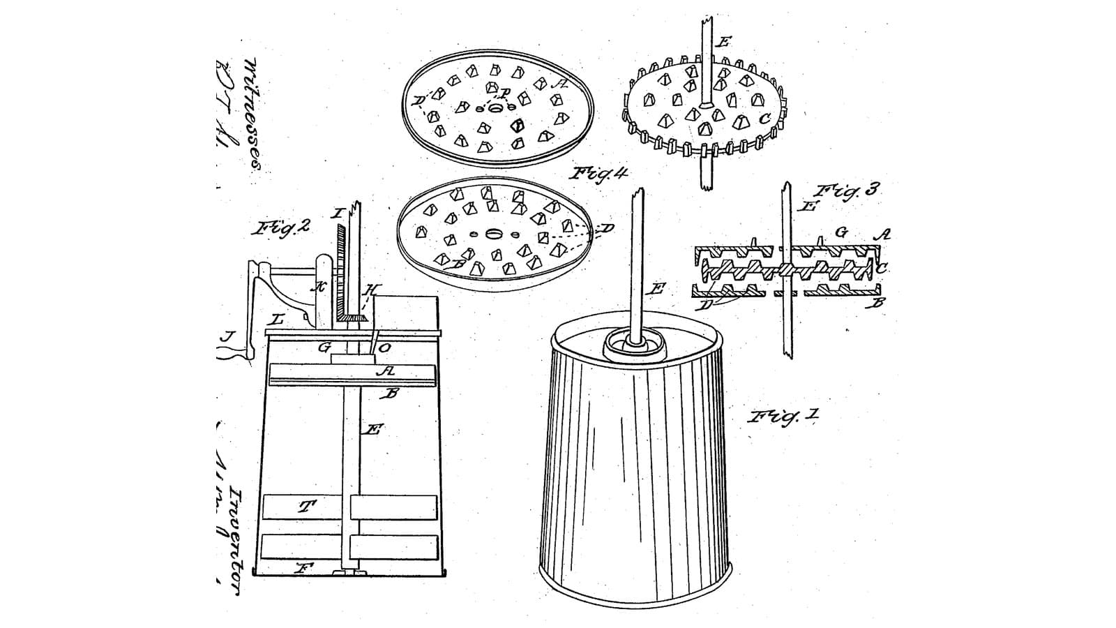
Toothed-Disk Pass Churn: Cream Poured In Passes Once Between Fixed Toothed Disks and a Toothed Wheel Spinning Between Them
by Buttercup
Woodworking
0
0
0
0
0
0

Churning Butter from Cream — The 5,000-Year-Old Fat Separation
by TheChef
CRAFT
60
0
0
0
0
0
CC0 Public Domain
This blueprint is released under CC0. You are free to copy, modify, distribute, and use this work for any purpose, without asking permission.
Support the Maker by purchasing products through their Blueprint where they earn a Maker Commission set by Vendors, or create a new iteration of this Blueprint and include it as a connection in your own Blueprint to share revenue.