ART
BEAUTY & WELLNESS
CRAFT
CULTURE & HISTORY
ENTERTAINMENT
ENVIRONMENT
FOOD & DRINKS
REVERSE ENGINEERING
SCIENCES
SPORTS
TECHNOLOGY
WEARABLES


The Diaphragm Valve: Nothing Crosses the Wall
Every valve in the previous rung has the same weakness, and it is not the seat. It is the **stem**: a rod that has to move through the pressure boundary, with a sliding seal round it that wears, weeps and has to be re-tightened. On clean cold water that is a nuisance. On acid, on slurry, on anything toxic or sterile, it is the whole problem.
Philip Keith Saunders's answer, developed from 1928 and patented through the 1930s, removes the stem from the fluid entirely. A flexible diaphragm **is** the wall; the stem presses on its dry outer face and pushes it down onto a sill cast across the body. Nothing penetrates anything.
It handles slurries that would jam a gate, acids that would eat a packing, and is the standard valve in pharmaceutical and semiconductor plants for exactly this reason.
Intermediate
About 3 hours
Instructions
1
1
Read the claim, and find the weir
Read the claim, and find the weir
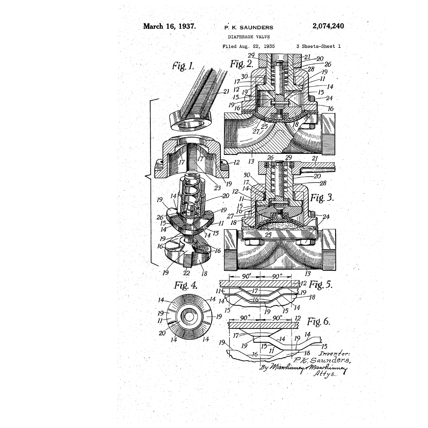
**US 2,074,240**, *Diaphragm valve*, **Philip Keith Saunders** of Wolverhampton, England, assignor to Saunders Inventions Limited; application **22 August 1935**, patented **16 March 1937**. Expired. The drawing on this page is the patent's own sheet 1.
Be clear about what this patent is and is not. Saunders developed the diaphragm valve itself from **1928–29**, and the original filings are South African and British; a number for those is **not asserted here** because the sources do not give one that checks out. This 1937 US patent is a refinement, and the specification says so in its first line — *diaphragm valves have numerous advantages* — before going on to claim an **actuating mechanism providing a varying leverage**, so that the compressor can be pushed down hard enough to hold the diaphragm *in the fully-closed* position without needing a huge handwheel.
That is worth reading as an engineering problem in its own right. The force needed rises steeply at the very end of the travel, when the diaphragm is finally being squeezed onto the sill — so a mechanism with constant leverage is either too heavy to turn at the end or too slow everywhere else.
Now find the **weir** in the figures: the raised sill cast across the middle of the body, with the flow passing over it. It is the feature that makes the type practical, and step 4 computes why.
2
2
Build one, and feel the force go up at the end
Build one, and feel the force go up at the end
A working diaphragm valve is one of the few valves a maker can actually build, because nothing needs to be round or lapped.
**The body.** A block — aluminium, or acrylic if you want to watch it work — with a through bore, and a raised sill left across the middle of the bore, rising to about two-thirds of the bore's height. Mill or file the top face flat: that face and the top of the sill must be in the same plane, because the diaphragm has to seal against both.
**The diaphragm.** A disc of silicone rubber sheet, 2–3 mm, cut a little larger than the bolt circle. Silicone is the right first choice: it is flexible, it takes heat, and the catalogue already has its chemistry rung.
**The compressor.** A shaped plate that presses the diaphragm onto the sill — flat with rounded edges, and as wide as the sill is long. A sharp-edged compressor cuts the diaphragm at its first closure.
**The bonnet.** A plate with a threaded hole, a bolt as the stem, and the compressor captive on its end. Four bolts clamping the diaphragm's rim between body and bonnet.
Assemble it, put water through it, and close it. **Feel what happens to the effort.** For most of the travel it is light; in the last fraction of a turn it climbs steeply, because you are no longer bending the diaphragm but squeezing it onto the sill. That is precisely the problem the 1937 patent's varying-leverage mechanism solves.
Watch through the acrylic if you built it clear. Note that the diaphragm rolls onto the sill from the middle outwards; it does not land flat.
Materials for this step:
 Silicone Rubber Sheet2 pieces
 PTFE Sheet1 piece
Tools needed:
 Bench Vise
 Drill Press
 Files (Hand File)
 Tap and Die Set
 Digital Caliper 6-Inch
 Spanner Set
 Torque Wrench
 Silicone Tubing
 Bucket
 Clear Safety Glasses
 Nitrile Gloves
3
3
Wear a diaphragm out, and see how it fails
Wear a diaphragm out, and see how it fails
The diaphragm is the valve's one consumable, and knowing its failure modes is the point of owning one.
Cycle your valve — open and closed, under pressure — counting. Stop every fifty cycles, take the bonnet off and look at the diaphragm under the microscope, particularly:
- **the line where it folds** as it comes off the sill;
- **the edge of the compressor**, where the material is pinched;
- **the clamped rim**, where it should not be moving at all.
Three distinct failures will appear, and each names a cause:
1. **Fatigue cracking at the fold** — normal end of life, and it is what the weir exists to postpone.
2. **A cut or a nick at the compressor edge** — the compressor is too sharp or too small. Fix the tool, not the diaphragm.
3. **Extrusion at the rim** — the clamping bolts are too loose, so pressure is pushing material out of the joint. It will leak next.
Then over-tighten deliberately and cycle again: crushing the diaphragm onto the sill does not seal it better, it destroys it faster. Diaphragm valves are the classic case where a torque wrench earns its place, and the manufacturer's figure is not advice.
Finally, try a **harder** material — a piece of PTFE sheet over the silicone, which is how chemical-service valves are actually made. It resists attack far better and flexes far worse, so it is always used as a facing over an elastomer backing rather than alone.
Materials for this step:
Silicone Rubber Sheet3 piecesPTFE Sheet1 pieceTools needed:
 Digital MicroscopeTorque WrenchSpanner SetDigital Caliper 6-Inch
 Stopwatch
 Pressure GaugeClear Safety GlassesNitrile Gloves
4
4
The force on the diaphragm, and what the weir saves
The force on the diaphragm, and what the weir saves
Loading Jupyter Notebook...
5
5
History and context
History and context
**Attribution.** US 2,074,240, *Diaphragm valve*, Philip Keith Saunders, Wolverhampton, assignor to Saunders Inventions Limited; filed 22 August 1935, granted 16 March 1937, expired. The drawing on this page is the patent's own. The original invention dates from **1928–29** and its first filings are not US; no number is asserted for those.
**Where it came from.** The story usually told is that Saunders, working in South Africa, was looking for a valve that would survive the abrasive slurries of mining. That is exactly the case a gate valve is worst at: grit packs into the seat groove and the wedge will not seat again. A diaphragm valve has no groove and no sliding surfaces in the fluid at all.
**Why it took over two whole industries.** Pharmaceutical and semiconductor plants adopted it almost exclusively, for a reason that has nothing to do with slurries: **there is nowhere for anything to hide**. No packing, no dead volume behind a seat, no crevice at a stem. The body can be drained completely and steam-sterilised in place. A valve you can prove is clean is worth a great deal in a process where you have to prove it.
**The idea to keep.** Saunders did not make a better seal around the stem — he **removed the reason for the seal**. That move, deleting a problematic interface rather than improving it, is one of the strongest patterns in engineering, and the catalogue holds several: the sealed cell that eats its own gas rather than venting it, the brushless motor that removes the commutator rather than improving the brushes, the integral rivet drawn from the sheet rather than fitted to it.
**Honest limits.** The diaphragm is a consumable and it sets the valve's whole envelope: temperature, chemical compatibility and pressure all belong to the elastomer, not to the body. Step 4 shows the force scaling that keeps the type small — large or high-pressure diaphragm valves are rare and expensive. The weir is a permanent restriction, so the pressure drop is worse than a gate's and the body cannot be drained fully unless it is installed with a deliberate slope. And it gives no indication of position: a diaphragm valve that has failed part-closed looks exactly like one that is fine.
Materials
2- 3 piecesPlaceholder
- 2 piecesPlaceholder
Tools Required
14- Placeholder
- Placeholder
- Placeholder
- Placeholder
- Placeholder
- Placeholder
- Placeholder
- Placeholder
- Placeholder
- Placeholder
- Placeholder
- Placeholder
- Placeholder
- Placeholder
Related Blueprints
These blueprints share knowledge with this one — techniques, materials, or principles that connect them in the learning graph.


CC0 Public Domain
This blueprint is released under CC0. You are free to copy, modify, distribute, and use this work for any purpose, without asking permission.
Support the Maker by purchasing products through their Blueprint where they earn a Maker Commission set by Vendors, or create a new iteration of this Blueprint and include it as a connection in your own Blueprint to share revenue.