ART
BEAUTY & WELLNESS
CRAFT
CULTURE & HISTORY
ENTERTAINMENT
ENVIRONMENT
FOOD & DRINKS
REVERSE ENGINEERING
SCIENCES
SPORTS
TECHNOLOGY
WEARABLES
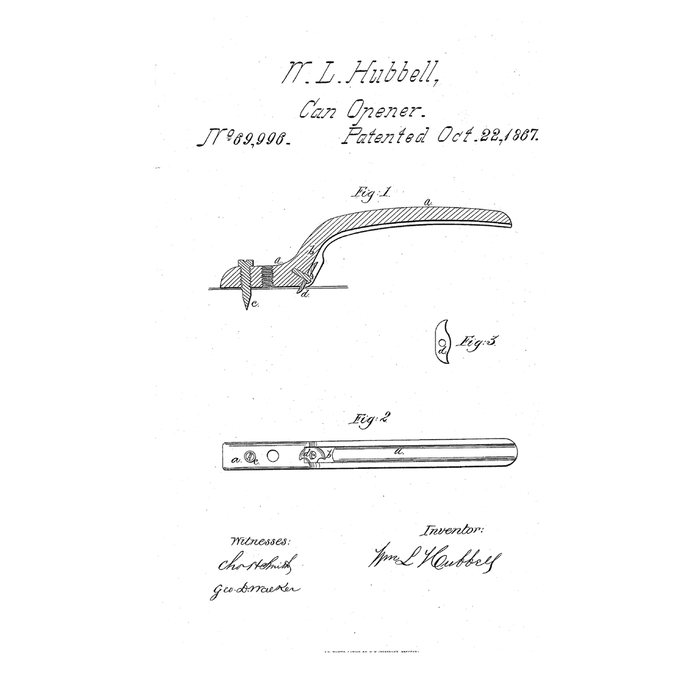


The Lifting-Cutter Can Opener: A Diagonal Blade Cuts Under and Holds the Disk
A can opener's knife can slip out of its cut, and the cut disk drops into the can.
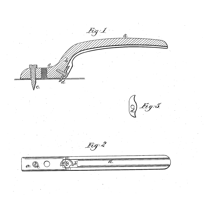
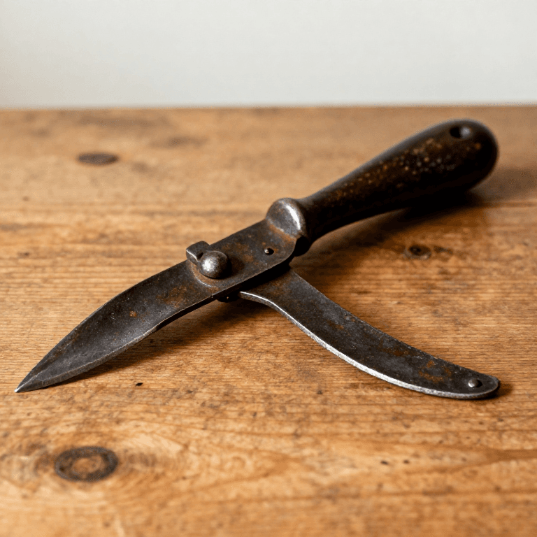
William L. Hubbell of Brooklyn, New York, received US 69,996, dated 22 October 1867, for a can opener made of a lever with a screw spike that fits any of several holes, to vary the size of the disk, and a cutter set diagonally "so as to cut under and lift up the said disk, and prevent the knife slipping out while in use," holding the disk until it is taken from the can.
This rung works out which hole suits which can, then builds the lever, spike and diagonal cutter and opens a can.
Intermediate
About 3 hours
Instructions
1
1
Spike hole against can size
Spike hole against can size
Loading Jupyter Notebook...
2
2
A turning cutter before it
A turning cutter before it
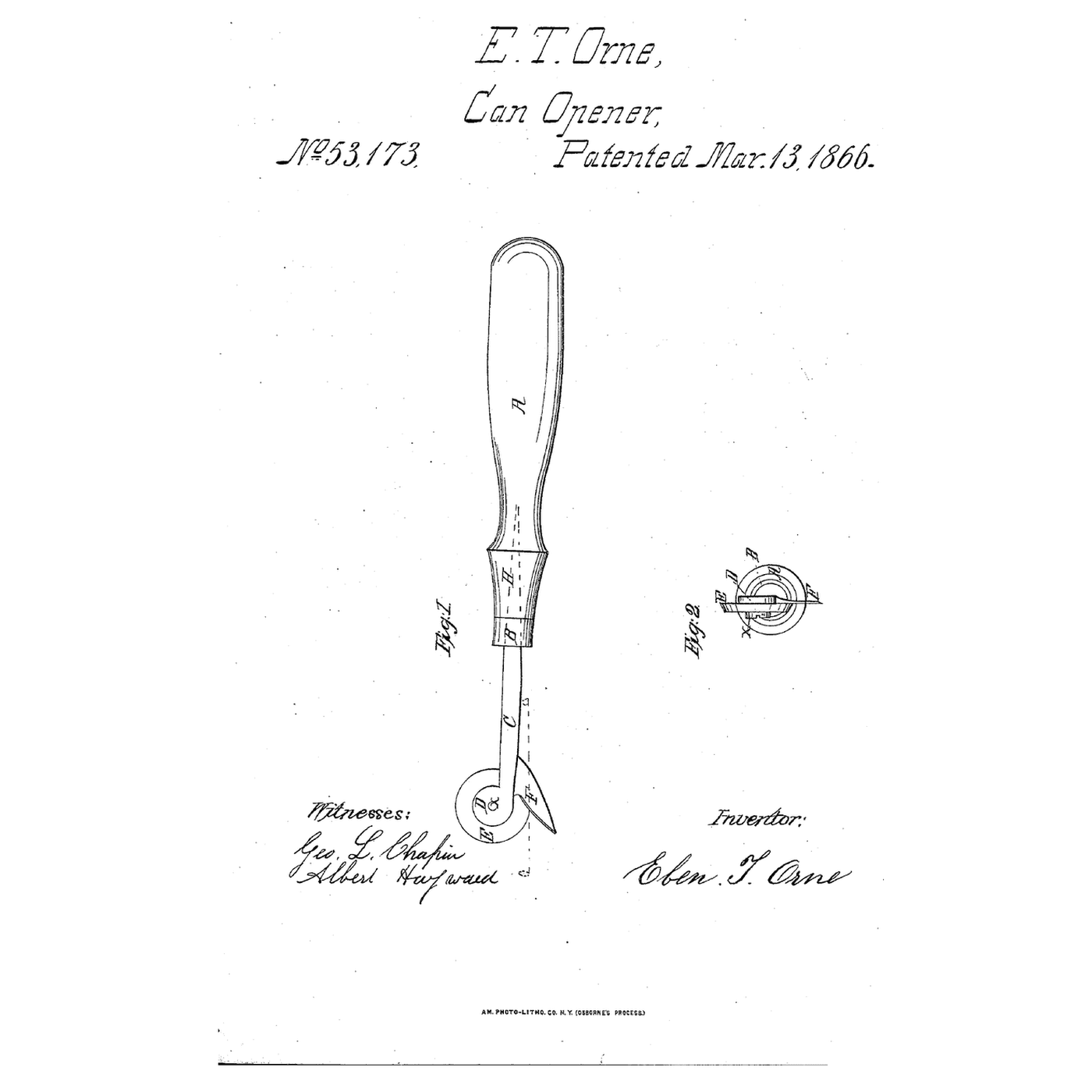
The embedded blueprint cuts round a can with a wheel and a fixed cutter. Hubbell turns a lever round a spike and inclines the cutter so it lifts what it cuts.
3
3
Read US 69,996
Read US 69,996
"The cutter d is set into a recess, formed by grooves, on the edges of the lever a, at the curved part b, so that one edge of the cutter projects below the under side of the lever at an inclination, as shown, so that the cutter is prevented from rising by its being below, and inclining inwards under the edge of the disk that is being cut out by revolving either the can or the opener."
4
4
Make the lever
Make the lever
Cut 180 mm of 25 × 3 mm flat bar and bend the last 20 mm down at about 40° in the vice. Drill and tap three M5 holes 25, 30 and 35 mm from the bend's foot.
Materials for this step:
 Mild Steel Flat Bar1 piece
Tools needed:
 Hacksaw
 Bench Vise
 Hammer
 Center Punch
 Cordless Drill
 Drill Bit Set
 Tap and Die Set
 Ruler
Ruler5
5
Slot the bent end
Slot the bent end
Saw a slot 1 mm wide and 12 mm deep across the bent end at 25° to the bar with the hacksaw.
Tools needed:
HacksawBench Vise Needle File Set
6
6
Make and set the cutter
Make and set the cutter
Cut a 16 × 18 mm cutter from 1 mm steel sheet and file both short ends to rounded cutting edges. Set it in the slot with epoxy so one end projects 5 mm below the bar, inclined inward.
Materials for this step:
 Mild Steel Sheet1 piece
 Two-Part Epoxy1 piece
Tools needed:
 Tin Snips
 Files (Hand File)
 Whetstone
 Clear Safety Glasses
7
7
Make the spike
Make the spike
File the end of an M5 screw to a long taper point. Screw it into the hole that suits the can.
Materials for this step:
 Machine Screws1 piece
Tools needed:
Bench ViseFiles (Hand File)8
8
The patent drawing
The patent drawing
US 69,996 drawing sheet, public domain (expired patent).
9
9
Open a can and lift the disk
Open a can and lift the disk
Stand a sealed can on the kitchen scale. Thrust the spike into the top's centre, press the cutter through and turn the lever round; read the peak load and time it. Lift the opener and see whether the disk comes with it.
Materials for this step:
 Tin Can1 piece
Tools needed:
 Digital Kitchen Scale
 Stopwatch
 Digital Caliper 6-Inch
 Leather Work Gloves
10
10
A cutter that rides up, slips or drops the disk
A cutter that rides up, slips or drops the disk
Lifting-cutter can opener troubleshooting.
Flow
Loading...
11
11
History and honest limits
History and honest limits
**William L. Hubbell** of Brooklyn, New York, signed his specification on 16 August 1867; US 69,996 is dated 22 October 1867. He wrote that earlier openers with semicircular knives, or tools to perforate and raise the edges, were costly and some were liable to slip. The cutter's edge is rounded outwardly so as not to draw the spike out, and both ends are shaped alike so it can be changed end for end.
**Honest limits.** Epoxy in a sawn slot stands in for his grooved recess, and the cutter is unhardened. Your loads and times are the result.
Materials
5- 1 piecePlaceholder
- 1 piecePlaceholder
- 1 piecePlaceholder
- 1 piecePlaceholder
- 1 piecePlaceholder
Tools Required
17- Placeholder
- Placeholder
- Placeholder
- Placeholder
- 1 vendor sell this, none ship to you yetPlaceholder
- Placeholder
- Placeholder
- Placeholder
- Placeholder
- Placeholder
- Placeholder
- Placeholder
- Placeholder
- Placeholder
- Placeholder
- Placeholder
- Placeholder
Related Blueprints
These blueprints share knowledge with this one — techniques, materials, or principles that connect them in the learning graph.
CC0 Public Domain
This blueprint is released under CC0. You are free to copy, modify, distribute, and use this work for any purpose, without asking permission.
Support the Maker by purchasing products through their Blueprint where they earn a Maker Commission set by Vendors, or create a new iteration of this Blueprint and include it as a connection in your own Blueprint to share revenue.