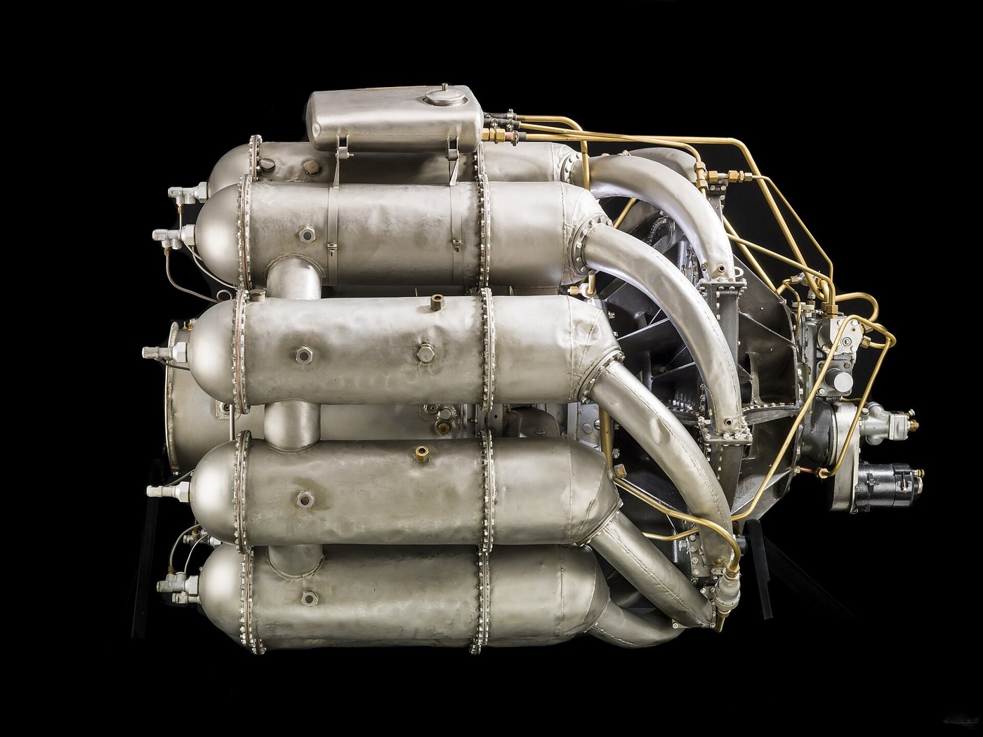


The Whittle Turbojet
Instructions
Read the hazards, because all three are serious
Read the hazards, because all three are serious
This blueprint involves fuel, heat and stored rotational energy at the same time. Each is manageable; together they demand a plan.
- Work outdoors or in a bay with a clear blast path and nothing combustible downstream.
- Keep a dry powder extinguisher within reach and know how to use it before you light anything.
- Never stand in the plane of the rotor while it is spinning — stand to the side, always.
- Wear hearing protection from the first run. A small turbine is far louder than it looks and the damage is cumulative and permanent.
- Fit a containment shield around the rotor.
The rotor is the hazard people underestimate. A turbine wheel at high rpm stores a great deal of energy, and if it bursts the fragments leave in the plane of rotation with enough energy to pass through a wall. Aircraft engines carry containment casings for this reason; a bench rig must too.
The fuel hazard is more obvious but no less real. Combustion is continuous rather than intermittent, so a leak does not misfire and stop — it feeds a fire that is already burning.
Exhaust gas leaves at several hundred degrees and is invisible. Mark the danger zone on the ground before the first run, not after someone walks through it.Materials for this step:
 Fire Extinguisher1 piece
 Steel Sheet1 sheet
Tools needed:
 Hearing Protection (Ear Defenders, SNR 30 dB)
 Face Shield
 Clear Safety GlassesFire Extinguisher
 Infrared Thermometer
Trace the cycle: suck, squeeze, burn, blow
Trace the cycle: suck, squeeze, burn, blow
The turbojet is a four-stroke engine whose four strokes happen in four PLACES rather than four moments.
- Sketch the flow path: intake, compressor, combustion chamber, turbine, nozzle.
- Against each station, mark what happens to pressure, temperature and velocity.
- Compare with the four strokes of a piston engine.
A piston engine does induction, compression, combustion and exhaust one after another in the same cylinder; a gas turbine does all four simultaneously in four different places. That is the whole reason it can be so much lighter for its power — nothing has to stop, reverse and start again, and no part of the machine is idle waiting its turn.
The key relationship, and the one that decides whether the engine runs at all: the turbine extracts only enough work to drive the compressor, and everything left over leaves as a fast jet. If the turbine takes too much there is no thrust; if it takes too little the compressor slows and the whole cycle collapses.
The Parsons steam turbine blueprint already in this catalogue is the direct ancestor of the turbine stage — Whittle did not have to invent how to extract work from a hot gas stream, that was fifty years old. What was new was closing the loop so the turbine drove the compressor that fed the combustion that drove the turbine.Materials for this step:
 Graph Paper1 pad
Tools needed:
 Protractor
 Digital Caliper 6-Inch
Build the centrifugal compressor, and see why Whittle chose it
Build the centrifugal compressor, and see why Whittle chose it
Whittle used a centrifugal impeller when axial compressors looked more elegant, and he was right for his decade.
- Machine or adapt a centrifugal impeller — an automotive turbocharger compressor wheel is the practical route and is what most bench turbines use.
- Fit it in a volute housing with a diffuser ring downstream.
- Drive it with compressed air or a motor and measure the pressure rise across it against rpm.
- Plot pressure ratio against speed.
Pressure rise climbs steeply with rpm — roughly with its square — which is why these engines only work at very high rotational speeds. The impeller throws air outward, converting shaft work into velocity; the diffuser then slows that fast air down and converts its velocity into pressure. Both halves are needed, and a compressor without a proper diffuser makes wind rather than pressure.
A single centrifugal stage gives a useful pressure ratio in one robust component, tolerates dirt and mismatched conditions, and is short. An axial compressor is more efficient and much slimmer in frontal area, but needs many stages, each a row of small aerofoils operating near their stall.
So Whittle’s choice was about what could be built reliably in 1937 rather than what was theoretically best, and it was the correct engineering judgement. Axial compressors won later, once the metallurgy and the aerodynamic understanding had caught up — but every small turbine and turbocharger today is still centrifugal, for exactly Whittle’s reasons.Materials for this step:
 Turbocharger Compressor Wheel1 pieceSteel Sheet1 sheet
 Ball Bearing2 pieces
Tools needed:
 Metal Lathe
 Milling Vise (4-inch)
 Dial IndicatorDigital Caliper 6-Inch
 Micrometer
 Digital Tachometer
 Pressure Gauge
 Torque WrenchClear Safety GlassesHearing Protection (Ear Defenders, SNR 30 dB)
Build the combustor and keep the flame alive
Build the combustor and keep the flame alive
Burning fuel in a hurricane is harder than it sounds, and the solution is deliberately anti-intuitive.
- Make a flame tube: an inner perforated liner inside an outer casing, so air can flow both through and around it.
- Drill the liner in zones — a small number of holes at the front for primary combustion air, more further back for dilution.
- Fit a swirler at the head to spin the incoming primary air.
- Fit a fuel injector and an igniter.
The swirler is the reason the flame does not simply blow out. Spinning the air creates a recirculation zone at the centre — a pocket where hot gas actually flows BACKWARD toward the injector, continuously re-igniting the incoming mixture. The flame is anchored to a standing eddy rather than to any surface.
The zoning matters as much. Fuel burns properly only near stoichiometric ratio, but the turbine downstream cannot survive stoichiometric temperatures. So only a fraction of the air is admitted where the burning happens, and the rest is added afterwards purely to dilute the gas down to something the turbine blades can tolerate. Most of the air passing through a jet engine never takes part in combustion at all — it is there to keep the fire away from the metal.
The liner is also cooled by that bypass air flowing along its inside face as a film. This is why flame tubes are drilled in such elaborate patterns: every hole size and angle is doing a specific job, and the pattern is the design.Materials for this step:
 Stainless Steel Tube (76mm)1 piece
 Stainless Steel Sheet (1mm)1 sheet
 Propane1 canister
 Spark Igniter Module1 piece
Tools needed:
 TIG Welder
 Drill Press
 File SetDigital Caliper 6-InchInfrared Thermometer
 Thermocouple with ReadoutFire ExtinguisherFace ShieldClear Safety GlassesHearing Protection (Ear Defenders, SNR 30 dB)
Run it, and find the two ways it destroys itself
Run it, and find the two ways it destroys itself
Both failure modes are worth understanding before you meet them.
- With the containment shield fitted and everyone clear of the rotor plane, start air on the compressor, establish fuel flow and ignite.
- Bring it up slowly, watching exhaust gas temperature continuously.
- Have a fuel shut-off within immediate reach and use it at the first sign of rising temperature you did not command.
The first failure is overtemperature. Turbine blades operate close to the limit of their material at the best of times; too much fuel and the exhaust gas temperature climbs, and turbine metal loses strength catastrophically as it approaches its limit — it does not bend, it stretches and lets go. Watch the temperature, not the rpm.
The second is runaway. A gas turbine has a genuinely unstable tendency: more fuel gives more energy, which gives more turbine work, which drives the compressor faster, which admits more air, which supports more fuel. Whittle’s first bench run in April 1937 did exactly this and accelerated out of control while the team ran for cover — the fuel governor, not the aerodynamics, is what makes a turbine safe.
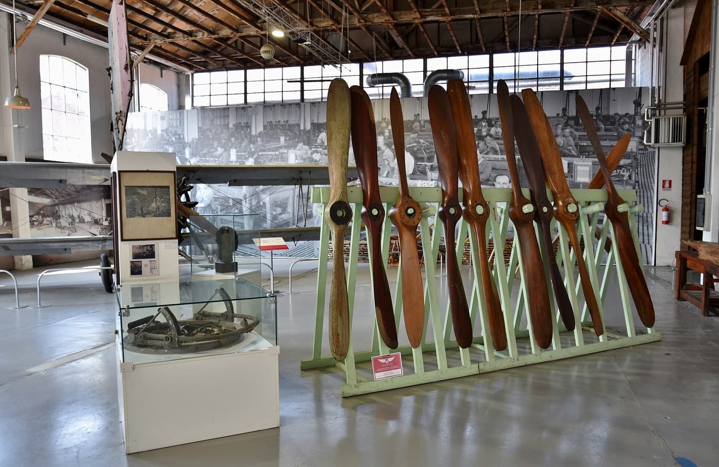
This is why the propeller wall was worth breaking through. A piston engine turns fuel into torque and then asks a propeller to turn torque into thrust, and the propeller runs out of capability near the speed of sound. The jet deletes the propeller entirely and produces thrust directly from the gas stream, so the sonic tip limit simply does not apply. The Gloster E.28/39 flew in May 1941 at around 550 km/h; within fifteen years jets were supersonic. That is what removing a limit rather than optimising against it looks like.Materials for this step:
Propane2 canisterThermocouple with Readout2 pieces Fuel Shut-Off Valve1 piece
Tools needed:
Digital TachometerInfrared Thermometer Thermal Imaging CameraThermocouple with ReadoutPressure GaugeFire ExtinguisherFace ShieldHearing Protection (Ear Defenders, SNR 30 dB)
 Smartphone with Slow-Motion VideoClear Safety Glasses
Materials
11- Placeholder
- Placeholder
- 1 padPlaceholder
- Placeholder
- Placeholder
- 1 piecePlaceholder
- 1 sheetPlaceholder
- 3 canisterPlaceholder
- 1 piecePlaceholder
- 2 piecesPlaceholder
- 1 piecePlaceholder
Tools Required
20- Placeholder
- Placeholder
- Placeholder
- Placeholder
- Placeholder
- Placeholder
- Placeholder
- Placeholder
- Placeholder
- Placeholder
- Placeholder
- Placeholder
- Placeholder
- Placeholder
- Placeholder
- Placeholder
- Placeholder
- Placeholder
- Placeholder
Related Blueprints
These blueprints share knowledge with this one — techniques, materials, or principles that connect them in the learning graph.

CC0 Public Domain
This blueprint is released under CC0. You are free to copy, modify, distribute, and use this work for any purpose, without asking permission.
Support the Maker by purchasing products through their Blueprint where they earn a Maker Commission set by Vendors, or create a new iteration of this Blueprint and include it as a connection in your own Blueprint to share revenue.