

Fellows Gear-Shaper Cutter (US 579,708): The 3D Models
Seven 3D models from Edwin R. Fellows's gear-shaper patent, US 579,708 (1897): the gear-shaper cutter of Fig. 11 with the 40-tooth gear and the 60-tooth internal ring gear it cuts, the sprocket-wheel cutter of Fig. 20 with its sprocket wheel, and the four-lobed cutter of Fig. 21 with the square bar it cuts.
Each model has its own step, after the step that explains it. The last step covers printing all seven.
Hướng dẫn
The cutter in Fig. 11
The cutter in Fig. 11
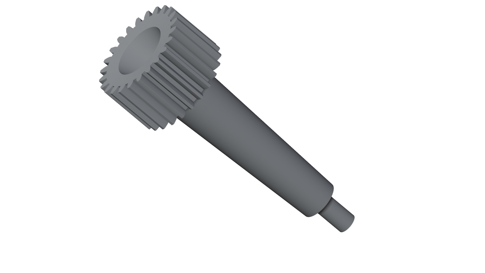
The gear-shaper cutter (Fig. 11) in 3D
The gear-shaper cutter (Fig. 11) in 3D
Its proportions are scaled from Fig. 11. The patent gives no dimensions, so the tooth count, module and pressure angle are stated standard choices. It is a display and teaching model, not a working tool.
Spin the cutter in the viewer and look at the dished cutting face and the tapered hollow. It was built in FreeCAD from an exact involute tooth profile and saved as one joined .blend mesh. It opens in free Blender.
Công cụ cần thiết:
 Máy tính để bàn
How the cutter made these teeth
How the cutter made these teeth
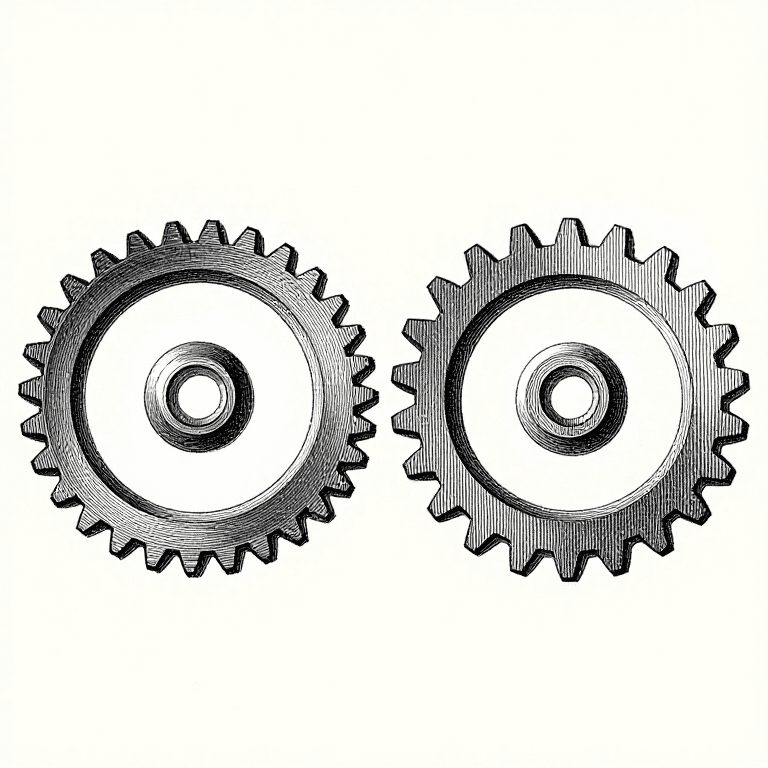
The 40-tooth gear it cuts, in 3D
The 40-tooth gear it cuts, in 3D
No tooth was drawn by hand. The flanks came out as true involutes, and the cutter's tips left a curved fillet at the root, as on a real shaped gear. The tooth count, face width and bore are stated choices; the patent gives no dimensions.
Spin the gear in the viewer and look at the curve where each flank meets the root. The cutter's tips made that curve, and no one drew it. It was built in FreeCAD and saved as one joined .blend mesh, editable in free Blender.
Công cụ cần thiết:
Máy tính để bànOne cutter, inside and out
One cutter, inside and out
The 60-tooth internal ring gear, in 3D
The 60-tooth internal ring gear, in 3D
Fellows counted this among his machine's advantages: one cutter cuts internal teeth as well as external ones. The flanks came out as true internal involutes. The tooth count, rim and face width are stated choices; the patent gives no dimensions.
Spin the ring in the viewer and look at the teeth on its inside. The cutter generated them, and no one drew them. It was built in FreeCAD and saved as one joined .blend mesh, editable in free Blender.
Công cụ cần thiết:
Máy tính để bànThe cutter in Fig. 20
The cutter in Fig. 20
The sprocket-wheel cutter (Fig. 20) in 3D
The sprocket-wheel cutter (Fig. 20) in 3D
It has seven broad teeth with narrower recesses between them, as his text says: "the teeth being longer than the intervening recesses." The patent gives no dimensions and no mathematical tooth form for this cutter, so its profile was traced off the patent drawing. The body behind the teeth is therefore an assumption: the shank, hollow and dished face are copied from the gear cutter of Fig. 11. It is a display and teaching model, not a working tool.
Spin the cutter in the viewer and look at its cutting face. The seven teeth follow Fellows's own outline: it was traced from the patent drawing, not drawn anew. It was built in FreeCAD and saved as one joined .blend mesh, editable in free Blender.
Công cụ cần thiết:
Máy tính để bànWhat Fig. 20 shows, and what was measured
What Fig. 20 shows, and what was measured
The sprocket wheel it cuts, in 3D
The sprocket wheel it cuts, in 3D
Its tooth count, centre distance and rim come from measurements on the drawing. The drawing shows the rim and one broken-off arm, so the arm count, hub, bore and thickness are stated choices.
Spin the wheel in the viewer. Its eighteen teeth were cut by rolling the Fig. 20 cutter against the rim, not drawn. Overlaid on Fellows's drawing, they sit on his finished tooth, on the tooth in the cutter's recess and on his dashed outline. It was built in FreeCAD and saved as one joined .blend mesh, editable in free Blender.
Công cụ cần thiết:
Máy tính để bànThe cutter in Fig. 21
The cutter in Fig. 21
What the drawing measures, and what the simulation found
What the drawing measures, and what the simulation found
The four-lobed cutter (Fig. 21) in 3D
The four-lobed cutter (Fig. 21) in 3D
The size is a stated choice. Fig. 21 shows the cutter only from its cutting end, so the body behind the lobes is copied from the Fig. 11 gear cutter.
Spin the cutter in the viewer and look at its cutting face. The four lobes are four circles in Fellows's proportions. It was built in FreeCAD and saved as one joined .blend mesh, editable in free Blender.
Công cụ cần thiết:
Máy tính để bànHow the square was cut
How the square was cut
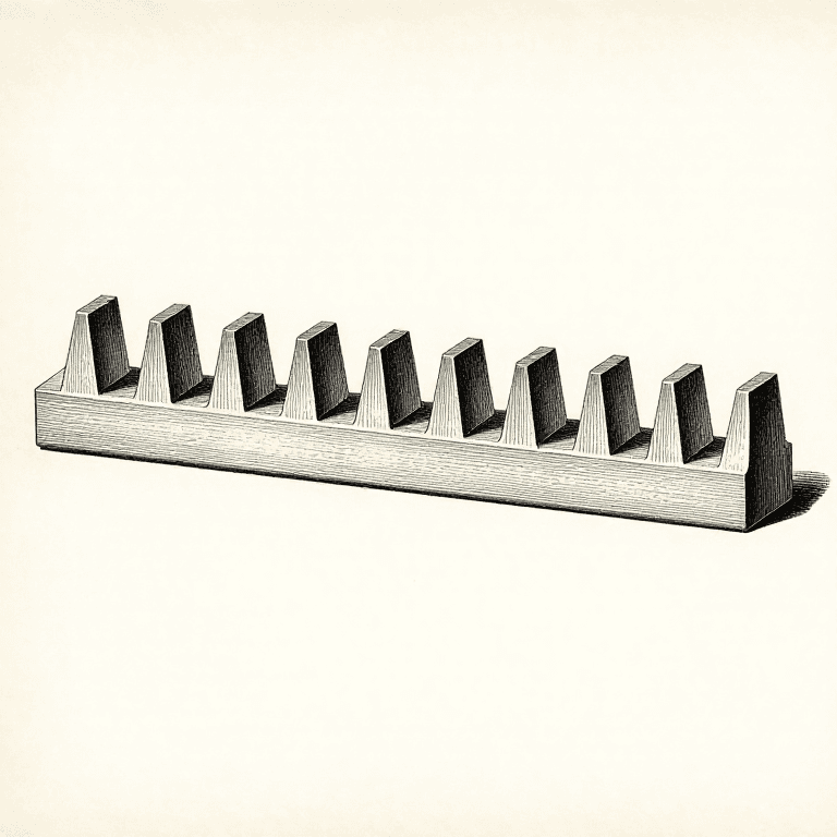
The square bar it cuts, in 3D
The square bar it cuts, in 3D
Fellows called the faces "plane surfaces". The simulation shows them as very nearly plane: each has about 1 mm of gentle waviness across a 47.6 mm face. The bar's length is a stated choice, because Fig. 21 shows only its cross-section.
Look at the bar end-on in the viewer. Each face is very nearly straight, with a gentle wave the four lobes leave behind. The rolling motion cut every face, and none was drawn. It was built in FreeCAD and saved as one joined .blend mesh, editable in free Blender.
Công cụ cần thiết:
Máy tính để bànPrint them
Print them
The three cutters: stand each on its cutting face with the shank up. The dished face is a near-flat overhang and the hollow has a 24 mm flat roof, so turn on supports from the build plate. The real cutters are hardened steel.
The 40-tooth gear: lay it flat on one face. It needs no supports. Two copies at 100 mm centres have no tip clearance and no backlash, which leaves no room for printing tolerance, so a printed pair is for studying the tooth form.
The internal ring gear: lay it flat on one face. It needs no supports, but the bed must be at least 180 mm across. Because of the interference stated above, it is not a working ring for the 40-tooth gear as drawn.
The sprocket wheel: lay it flat on one face. It needs no supports, but the bed must be at least 187 mm across.
The square bar: stand it on one end. It needs no supports. Hold a straightedge across a face to see the slight waviness the cutter leaves.
PLA is fine for a display model.
Vật liệu cho bước này:
 Sợi nhựa PLA - đen1 bộ
Công cụ cần thiết:
 Máy in 3D
Vật liệu
1- Tạm thời
Tệp thiết kế
7Vật liệu bản thiết kế liên kết

Blueprint liên quan
Các blueprint này chia sẻ kiến thức — kỹ thuật, vật liệu hoặc nguyên tắc

CC0 Phạm vi công cộng
Bản thiết kế này được phát hành theo CC0. Bạn tự do sao chép, sửa đổi, phân phối và sử dụng cho bất kỳ mục đích nào mà không cần xin phép.
Hỗ trợ nhà sáng tạo bằng cách mua sản phẩm qua bản thiết kế, nơi họ nhận Hoa hồng nhà sáng tạo do nhà bán hàng đặt, hoặc tạo phiên bản mới và kết nối trong bản thiết kế riêng để chia sẻ doanh thu.