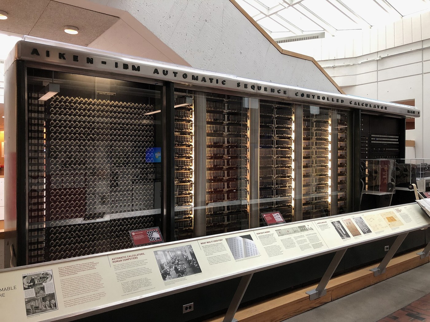


Logic Gates from Relays
Hướng dẫn
Start from the telegraph relay
Start from the telegraph relay
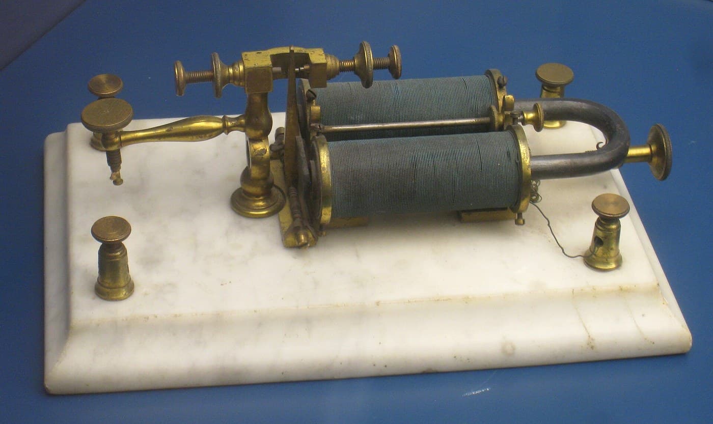
Build or re-read the relay first. It was invented to solve a completely different problem — a telegraph signal too weak to travel further, restored by using it to operate a local switch on a fresh battery.
Note the property that matters here and mattered not at all to its inventors: the thing that operates the switch is the same KIND of thing the switch controls. A lever needs a hand; a relay needs only another relay. That closure under composition is what makes logic possible, and it was sitting unused in telegraph offices for eighty years.
Wire AND, OR and NOT from contacts
Wire AND, OR and NOT from contacts
Three circuits, and every digital device ever built is made of them.
- AND: wire two relay contacts in SERIES between supply and lamp. The lamp lights only if both coils are energised.
- OR: wire two contacts in PARALLEL. The lamp lights if either coil is energised.
- NOT: use a normally-CLOSED contact. The lamp lights when the coil is NOT energised.
- Build all three and fill in a truth table for each by trying every input combination.
Series is AND, parallel is OR, normally-closed is NOT. That is Shannon's entire correspondence, and it is worth pausing on how unreasonable it is that a topology of wires should match an algebra of propositions.
Now the payoff: because it IS algebra, you can simplify circuits symbolically. De Morgan's laws say NOT(A AND B) equals NOT A OR NOT B — which means the same function can be built two different ways, and you pick whichever needs fewer contacts. Engineers had been optimising relay circuits by intuition; after 1937 they optimised them by algebra.Vật liệu cho bước này:
 Rơ le4 cái
 Bộ LED báo hiệu1 bộ
 Bộ điện trở1 bộ
 Bo mạch lỗ / bo mạch thử1 cái
 Dây đấu nối1 reel
Công cụ cần thiết:
 Trạm hàn thiếc
 Đồng hồ vạn năng số cấp phòng thí nghiệm
 Nguồn điện bàn điều chỉnh được
 Kính bảo hộ trong suốt
Build the same logic as blocks
Build the same logic as blocks
Không gian làm việc Blockly
Loading Blockly workspace...
Công cụ cần thiết:
 Máy tính để bàn
Simulate, simplify, and count the contacts
Simulate, simplify, and count the contacts
Công cụ cần thiết:
Máy tính để bànMeasure the switching time, and find the ceiling
Measure the switching time, and find the ceiling
Relay logic works perfectly and is slow. Measure exactly how slow, because that number ends the era.
- Drive a relay coil with a square wave and put the oscilloscope on both the drive and the contact output.
- Measure the delay from coil energising to contacts closing, and again for release.
- Watch the contact closure closely at high sweep speed.
- Chain three relays so each drives the next, and measure the total delay.
A relay takes something like 5 to 20 milliseconds to switch, and the contacts BOUNCE for a millisecond or two after closing. Chain them and the delays add, so a computation passing through fifty gates takes most of a second.
The bounce is its own problem: a single logical transition arrives as a burst of several, and any counter downstream counts them all. Debouncing exists because a mechanical contact does not close once.
So the ceiling is mechanical, not logical. The algebra is fine and the relay is honest; it simply has mass, and mass takes time to move. The escape is a switch with no moving parts at all — the vacuum tube, which switches in microseconds, and then the transistor, which does it without the heat. That is the rest of this batch.Vật liệu cho bước này:
Rơ le3 cáiBộ điện trở1 bộCông cụ cần thiết:
 Máy hiện sóng
 Máy phát hàmĐồng hồ vạn năng số cấp phòng thí nghiệmNguồn điện bàn điều chỉnh được
Vật liệu
5- 7 cáiTạm thời
- 1 bộTạm thời
- Tạm thời
- Tạm thời
- 1 reelTạm thời
Công cụ yêu cầu
7- Tạm thời
- Tạm thời
- Tạm thời
- Tạm thời
- Tạm thời
- Tạm thời
Blueprint liên quan
Các blueprint này chia sẻ kiến thức — kỹ thuật, vật liệu hoặc nguyên tắc

CC0 Phạm vi công cộng
Bản thiết kế này được phát hành theo CC0. Bạn tự do sao chép, sửa đổi, phân phối và sử dụng cho bất kỳ mục đích nào mà không cần xin phép.
Hỗ trợ nhà sáng tạo bằng cách mua sản phẩm qua bản thiết kế, nơi họ nhận Hoa hồng nhà sáng tạo do nhà bán hàng đặt, hoặc tạo phiên bản mới và kết nối trong bản thiết kế riêng để chia sẻ doanh thu.