Colaboração
ARTE
BELEZA E BEM-ESTAR
ARTESANATO
CULTURA E HISTÓRIA
ENTRETENIMENTO
MEIO AMBIENTE
COMIDA E BEBIDAS
ENGENHARIA REVERSA
CIÊNCIAS
ESPORTES
TECNOLOGIA
TECNOLOGIA VESTÍVEL
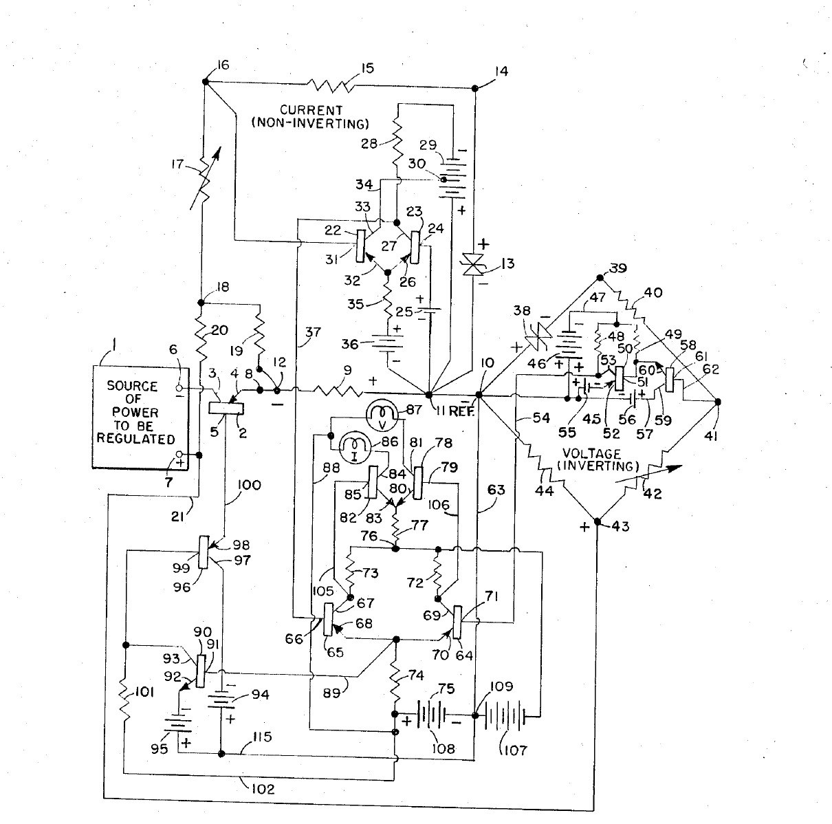


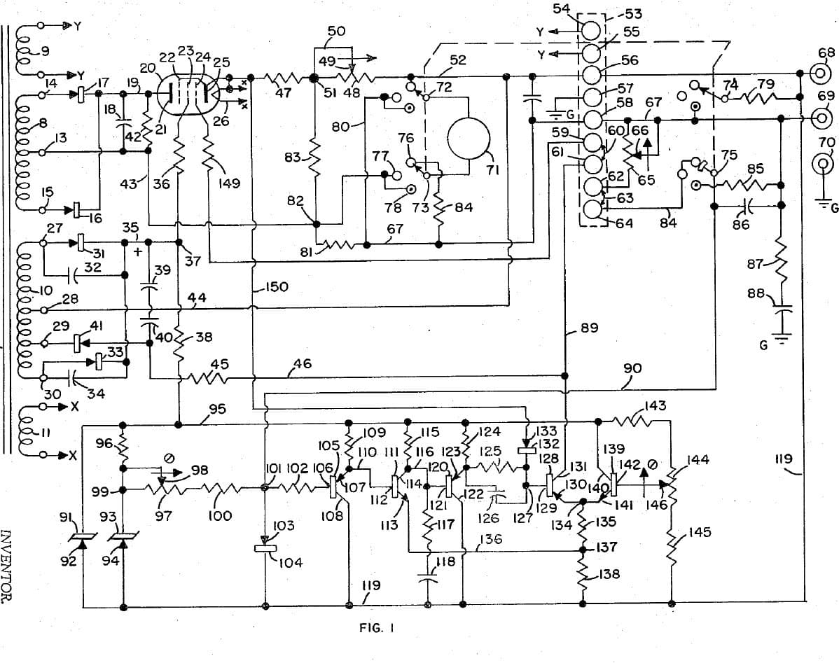
Adjustable Bench Power Supply: Constant Voltage / Constant Current with Cross-Over Lamps (Gately, Forbro, US 3,303,411, 1967)
An all-transistor bench supply with two knobs: one sets the voltage, the other the current. It holds the set voltage until the load tries to draw more than the set current, then switches at once to holding the current, and back again, with no in-between state. Two lamps show which mode is in control.
Result: an adjustable constant-voltage / constant-current DC supply with mode lamps.
Source: J. R. Gately (Forbro Design), US 3,303,411 (1967). Unknown: all component values and ratings. Builds on the same inventor's 1966 current-limited supply. Picture: the patent drawing.
Avançado
Unknown
Instruções
1
1
Build the raw supplies
Build the raw supplies
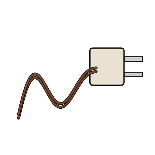
In a case, wire the cord through a switch and fuse to two power transformers, each with rectifiers and a filter: one gives the main power to be regulated, the other the bias supplies, held steady by Zener diodes. Not given: the voltages. Ours: the case, switch and fuse.
Materiais para este passo:
 Caixa de alumínio1 peça
 Cabo flexível com ficha1 peça
 Interruptor de alavanca1 peça
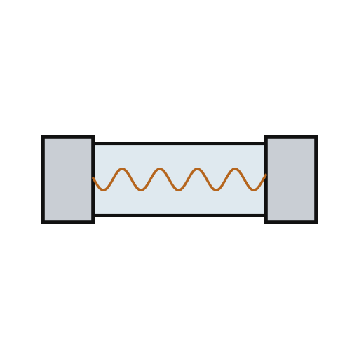 Fusível1 peça
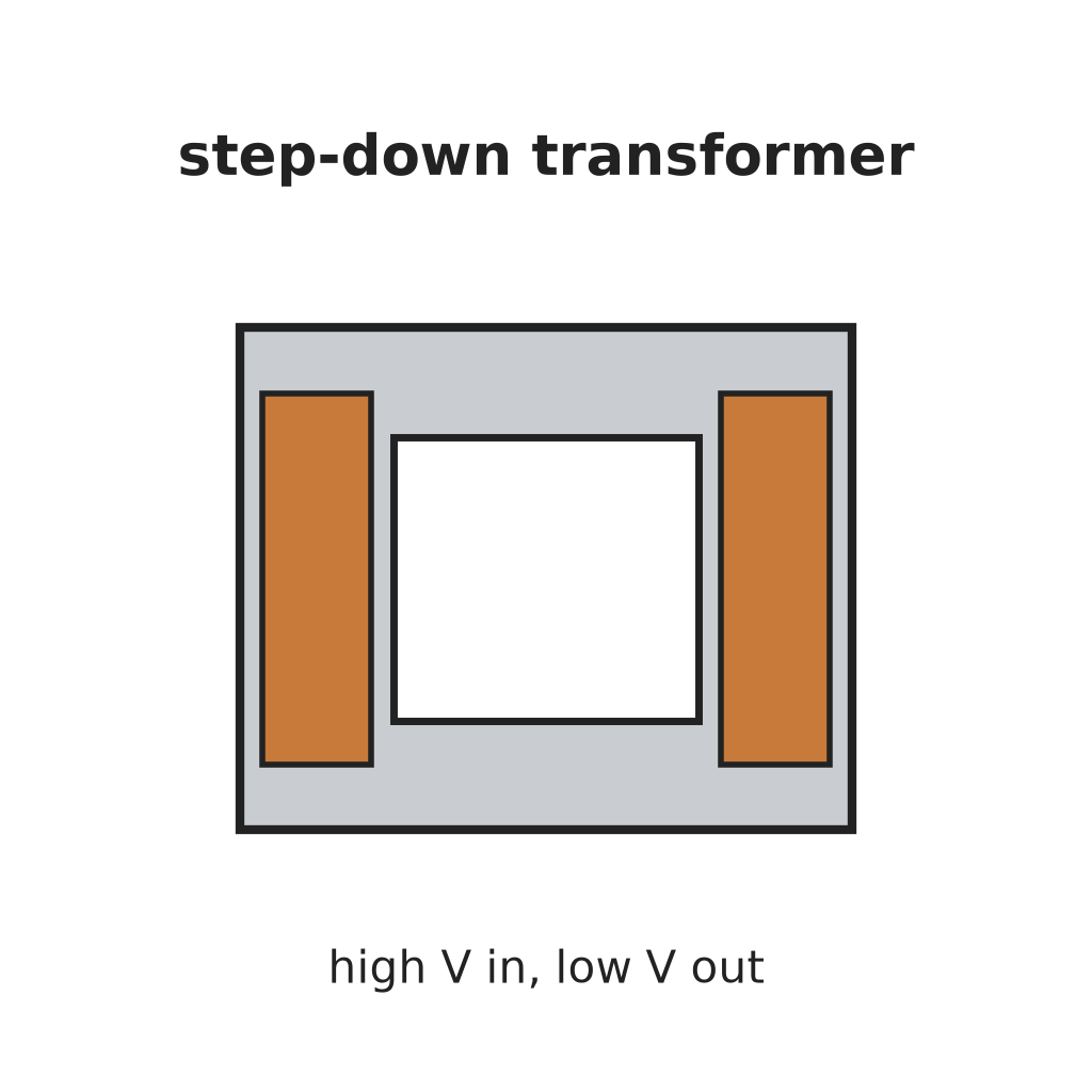 Transformador Abaixador2 peças
 Díodo6 rectifiers
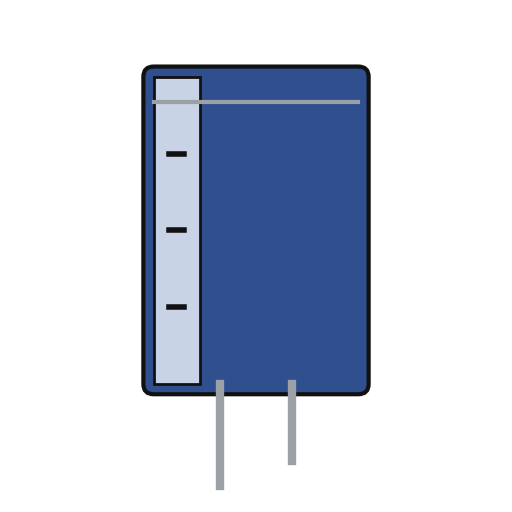 Condensador eletrolítico3 filters
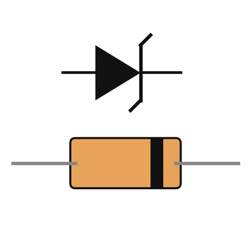 Díodo Zener2 bias
Ferramentas necessárias:
 Berbequim de mão
 Conjunto de chaves de fendas
2
2
Fit the pass transistor and current bridge
Fit the pass transistor and current bridge
Put a power transistor on a heat sink in series with the output: collector to the negative supply, emitter through a current-sensing resistor to the negative output terminal. Make the current bridge from the sensing resistor, a reference Zener, a reference resistor and the adjustable current-control resistor: the output current is proportional to its setting. A small trimming resistor sets the maximum current. Not given: the values.
Materiais para este passo:
 Transístor de potência1 series pass
 Dissipador de calor1 peçaDíodo Zener1 current reference
 Reóstato1 current control
 Resistência1 sensing, reference, trim set
 Borne de painel2 output + and -
Ferramentas necessárias:
 Ferro de soldar
3
3
Build the voltage bridge
Build the voltage bridge
Make the voltage bridge from a reference Zener, a reference resistor, the adjustable voltage-control resistor and the load itself across the output. A small trimming resistor sets the maximum voltage. Add two resistors that feed the current bridge enough extra to cover the voltage bridge's own current and any voltmeter across the output, so low currents are still held exactly.
Materiais para este passo:
Díodo Zener1 voltage referenceReóstato1 voltage controlResistência1 reference, trim, compensation setFerramentas necessárias:
Ferro de soldar4
4
Build the amplifiers and cross-over
Build the amplifiers and cross-over
Give each bridge an error amplifier. Feed the two amplified errors to the bases of a pair of transistors sharing one emitter resistor: whichever base is the more negative takes control and cuts the other off, so the supply is always cleanly in voltage mode or current mode. Amplify the shared emitter signal through two more transistors to drive the pass transistor's base. Add an emitter-follower clamp on the bias line. Not given: the transistor types.
Materiais para este passo:
 Placa de circuito impresso1 peça
 Sortido de transístores1 error amplifiers, cross-over pair, drivers, clampResistência1 conjunto
 Potenciómetro1 clamp divider
 Fio de solda1 as needed
Ferramentas necessárias:
Ferro de soldar5
5
Fit the mode lamps and use it
Fit the mode lamps and use it
From the cross-over pair, drive two lamp transistors, each lighting one lamp: one for voltage mode, one for current mode. In use, set the voltage and the current limit. With a light load the voltage lamp is lit and the voltage holds; if the load tries to draw more than the set current, the supply switches to holding the current and the current lamp lights.
Materiais para este passo:
Sortido de transístores1 two lamp drivers Casquilho de lâmpada2 peças
 Lâmpada2 peças
Ferramentas necessárias:
Conjunto de chaves de fendasMateriais
19- 1 peçaReferência
- 1 peçaReferência
- Referência
- 1 peçaReferência
- 2 peçasReferência
- 6 rectifiersReferência
- 3 filtersReferência
- 1 voltage referenceReferência
- 1 series passReferência
- 1 peçaReferência
- 1 voltage controlReferência
- 1 conjuntoReferência
- Referência
- Referência
- 1 two lamp driversReferência
- Referência
- 1 as neededReferência
- 2 peçasReferência
- 2 peçasReferência
Ferramentas necessárias
3- Referência
- Referência
- 2 vendors sell this, none ship to you yetReferência
Este projeto faz

Blueprints relacionados
Estes blueprints compartilham conhecimento — técnicas, materiais ou princípios
CC0 Domínio Público
Este blueprint é liberado sob CC0. Você é livre para copiar, modificar, distribuir e usar este trabalho para qualquer finalidade, sem pedir permissão.
Apoie o Maker comprando produtos através do Blueprint, onde ele ganha uma Comissão Maker definida pelos vendedores, ou crie uma nova versão deste Blueprint e inclua-o como conexão no seu próprio Blueprint para compartilhar receita.