Colaboração
ARTE
BELEZA E BEM-ESTAR
ARTESANATO
CULTURA E HISTÓRIA
ENTRETENIMENTO
MEIO AMBIENTE
COMIDA E BEBIDAS
ENGENHARIA REVERSA
CIÊNCIAS
ESPORTES
TECNOLOGIA
TECNOLOGIA VESTÍVEL
Shifting-Gear Grinding-Disk Churn: One Crank Wheel Is Thrown Into Gear With the Wings Below, the Grinding Disk Above, or Both
Buttercup

Criado por

Buttercup

12. novembro 2026IE
8
0
0
0
0

Shifting-Gear Grinding-Disk Churn: One Crank Wheel Is Thrown Into Gear With the Wings Below, the Grinding Disk Above, or Both

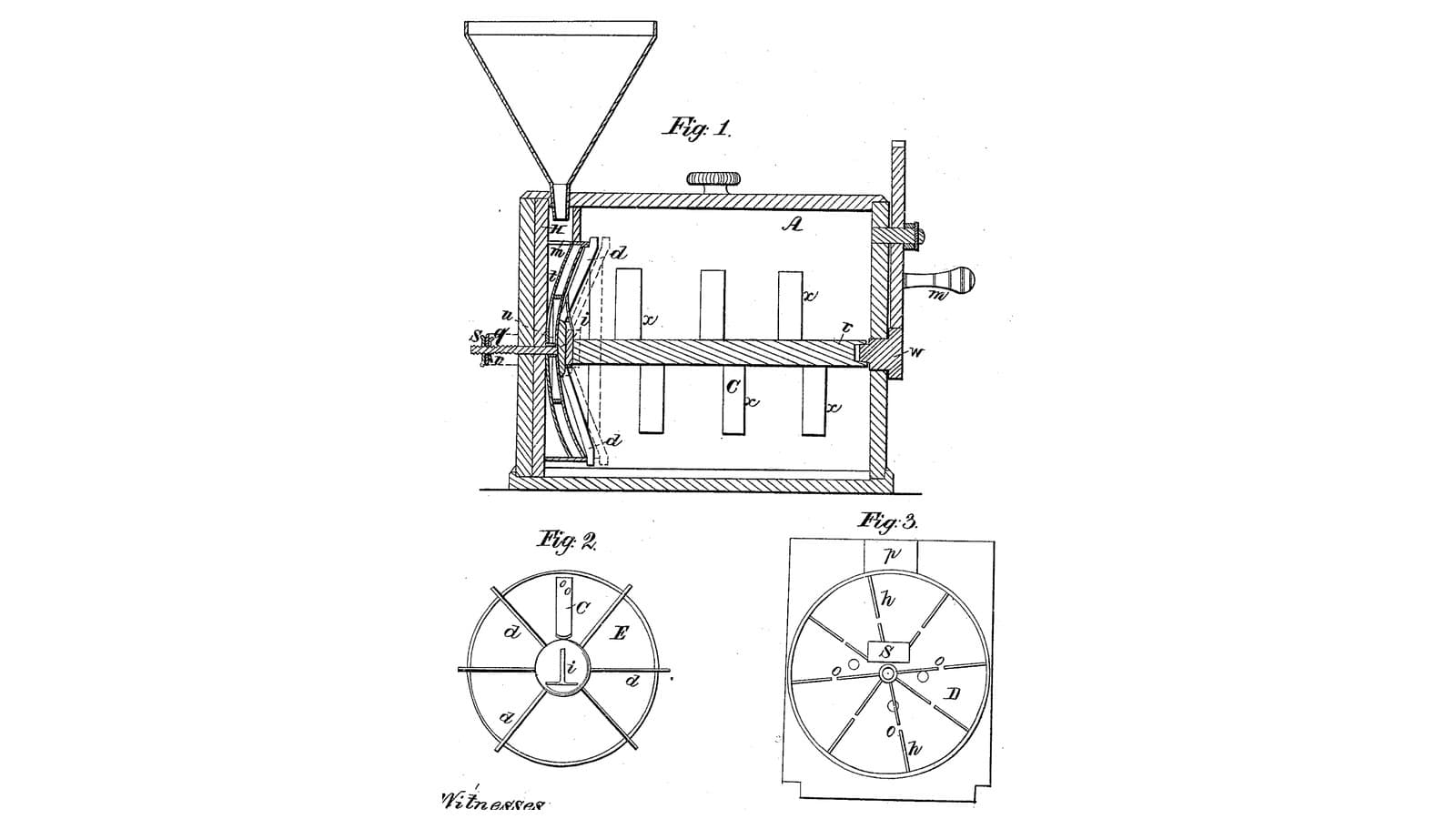
John Fowler and W. L. Walter of Homer, New York, received US 32,939, dated 30 July 1861, for a box churn with two working parts on one crank. High in the box a turning disk grinds the cream poured from a hopper against a fixed ribbed disk, and the cream falls below, out of their way; low in the box a shaft of wings gathers the butter. The crank wheel rides on a bar that slides and tilts in two guides on the box's side, so it can be put in gear with the disk alone, the wings alone, or both, and pinned there. The patent gives no sizes; every size here is ours.
Avançado
About 3 days

Instruções

1

One wheel, two pinions

A carregar o notebook Jupyter…
2

Cream ground once between disks as it is poured in, three months before

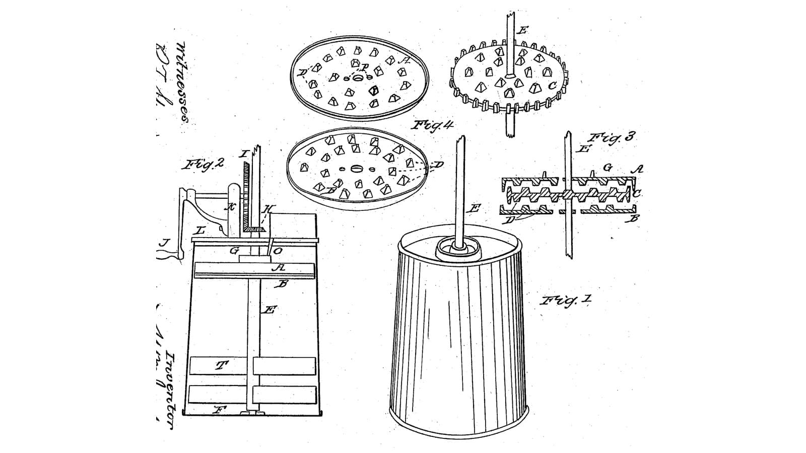
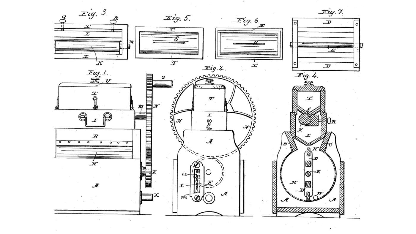
Jackson and Clarke grind the cream in a disk pack over the beaters. Fowler and Walter put the disks to one side and let one crank drive either disks or wings.
3

Read US 32,939

"By having the wheel H, attached to the bar G, and the latter arranged as shown, the disk b, may be rotated without the shaft B, or the latter may be rotated without the former or both rotated simultaneously as may be desired. This is an important feature of the invention for it is frequently necessary to use the disks without the wings or gatherers and vice versa."
4

Body A and lid

Glue up a hardwood box A 300 mm wide, 360 long and 320 deep inside, from 20 mm boards, joints sealed with silicone sealant. Bore one end 16.6 mm at 80 and 240 mm above the inside floor on its centre line for the shafts B and E, and the far end 16.6 mm at 80 mm for B's other bearing. Cut a hardwood lid with a 14 mm hole 25 mm off the centre line and 13 mm in from the geared end, for the hopper's spout.

Materiais para este passo:

Tábua de madeira de leiTábua de madeira de lei4 peças
Cola de madeiraCola de madeira1 peça
Vedante de siliconeVedante de silicone1 peça
Parafusos para madeiraParafusos para madeira30 peças

Ferramentas necessárias:
Serra de mesaSerra de mesa
Berbequim sem fiosBerbequim sem fios
Jogo de brocasJogo de brocas
Conjunto de brocas de páConjunto de brocas de pá
Sargento de barraSargento de barra
Conjunto de chaves de fendasConjunto de chaves de fendas
Fita métricaFita métrica
5

Shaft B with wings C and pinion D

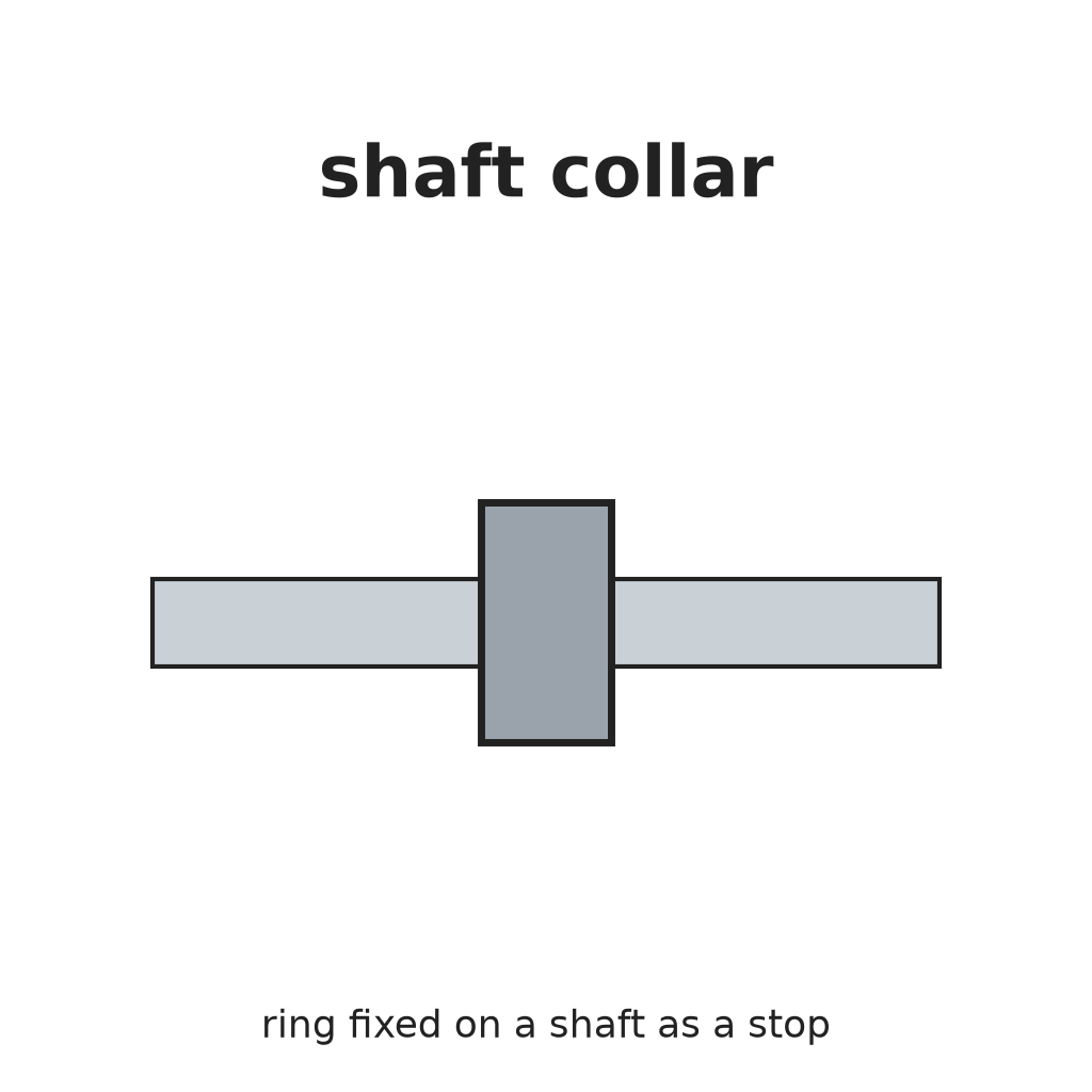
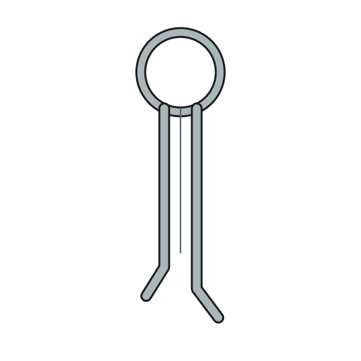
Cut a 16 mm stainless shaft B 432 mm long. Screw two pairs of hardwood wings C 70 x 80 x 20 mm through hardwood hubs on it, a quarter turn apart, one pair 70 to 150 mm from the geared end and one 220 to 300. Run it through both ends with shaft collars and pin a pinion D on its outer end 6 mm outside the box.

Materiais para este passo:

Varão de aço inoxidávelVarão de aço inoxidável1 peça
Tábua de madeira de leiTábua de madeira de lei1 peça
Parafusos para madeiraParafusos para madeira8 peças
Shaft CollarShaft Collar2 peças
ContrapinoContrapino2 peças
Filamento PETGFilamento PETG1 peça

Ferramentas necessárias:
Impressora 3D de filamento (FDM)Impressora 3D de filamento (FDM)
Serra de mesaSerra de mesa
Berbequim sem fiosBerbequim sem fios
Jogo de brocasJogo de brocas
Serra de arco para metaisSerra de arco para metais
Limas (lima de mão)Limas (lima de mão)
Conjunto de chaves de fendasConjunto de chaves de fendas
6

Print the pinions D and d (two)

A pinion: 16 teeth, module 2.5, 12 mm thick, 16.2 mm bore. Print two. PETG, 0.2 mm layers, 30 % infill, 4 walls.
Arquivo de designSTLCC0 - Free
7

Print the grinding disk b

The turning disk: 110 mm across, 6 thick, with two rings of ledges c 3 mm high at 40 and 50 mm out on its face, 16.2 mm bore. PETG, 0.2 mm layers, 30 % infill, 4 walls.
Arquivo de designSTLCC0 - Free
8

Print the hopper F

The hopper: a funnel 80 mm across on a 14 mm spout long enough to reach behind the fixed disk. PETG, 0.2 mm layers, 30 % infill, 4 walls.
Arquivo de designSTLCC0 - Free
9

Disks a and b, shaft E, pinion d and hopper F

Cut a 6 mm HDPE disk a 120 mm across with a 60 mm centre opening, glue twelve HDPE ribs 26 x 6 x 3 mm radially on its face, and screw it inside the geared end on three 10 mm stainless standoffs 25 mm long, around the upper shaft hole, ribs inward. Cut a 16 mm stainless shaft E 120 mm long, push it through the end and the disk a's opening, pin the disk b on its inner end with its ledges 3 mm from a's ribs, and the pinion d on its outer end. Set the hopper F in the lid so its spout drops into the space behind a, beside the shaft.

Materiais para este passo:

Chapa de PEADChapa de PEAD1 peça
Cola de madeiraCola de madeira1 peça
Varão de aço inoxidávelVarão de aço inoxidável2 peças
Parafusos para madeiraParafusos para madeira3 peças
ContrapinoContrapino2 peças
Shaft CollarShaft Collar1 peça
Filamento PETGFilamento PETG1 peça

Ferramentas necessárias:

Impressora 3D de filamento (FDM)Impressora 3D de filamento (FDM)
BússolaBússola
Serra tico-ticoSerra tico-tico
Conjunto de brocas de páConjunto de brocas de pá
Serra de arco para metaisSerra de arco para metais
Berbequim sem fiosBerbequim sem fios
Jogo de brocasJogo de brocas
Conjunto de chaves de fendasConjunto de chaves de fendas
10

Print the crank wheel H

The crank wheel: 48 teeth, module 2.5, 12 mm thick, 12.2 mm bore. PETG, 0.2 mm layers, 30 % infill, 4 walls.
Arquivo de designSTLCC0 - Free
11

Bar G, guides e, e', wheel H and pin a*

Cut a mild steel flat bar G 470 x 24 x 6 mm, drill it 12.2 mm for H's axle 210 mm from one end and a row of 6 mm holes near the other end. Make two hardwood guides: e, a block with a slot just wide enough for the bar, screwed to the geared end level with the gap between the pinions; e', with a slot 60 mm tall so the bar's end can rise and fall, and a row of 6 mm holes across it. Fit a 12 mm stainless axle in the bar, the wheel H on it between the two pinions, and a crank handle on H's face. Slide the bar into the guides and hold it with a 6 mm pin a* through e' and the bar.

Materiais para este passo:

Barra chata de aço macioBarra chata de aço macio1 peça
Tábua de madeira de leiTábua de madeira de lei1 peça
Parafusos para madeiraParafusos para madeira8 peças
Varão de aço inoxidávelVarão de aço inoxidável1 peça
ContrapinoContrapino2 peças
Cavilhas de madeira duraCavilhas de madeira dura1 peça
Filamento PETGFilamento PETG1 peça

Ferramentas necessárias:

Impressora 3D de filamento (FDM)Impressora 3D de filamento (FDM)
Serra de arco para metaisSerra de arco para metais
Limas (lima de mão)Limas (lima de mão)
Torno de bancadaTorno de bancada
Berbequim sem fiosBerbequim sem fios
Jogo de brocasJogo de brocas
Conjunto de formões para madeiraConjunto de formões para madeira
Conjunto de chaves de fendasConjunto de chaves de fendas
12

The build in 3D

FreeCAD model of this build, half the box cut away: the wing shaft low in the box, the fixed ribbed disk and the turning ledged disk high at the geared end, the hopper, and outside the crank wheel on its bar in two guides, meshing both pinions.
Arquivo de designBLENDCC0 - Free
13

Churn: grind, then gather

Pin the bar so H meshes the disk's pinion d only. Turn the crank and pour about 12 litres of heavy cream at about 15 °C, checked with the thermometer, slowly into the hopper, timing it; it is ground between the disks and falls to the bottom. Then move the bar so H meshes the wings' pinion D (or both) and turn to gather the butter. Lift the lid, take out the butter, pour the buttermilk into a bowl, wash the butter in cold water until it runs clear, salt and weigh it.

Materiais para este passo:

Natas para baterNatas para bater12 l
Sal marinho grossoSal marinho grosso1 peça
ÁguaÁgua1 peça

Ferramentas necessárias:

Termómetro de sonda permanenteTermómetro de sonda permanente
CronómetroCronómetro
Balança digital de cozinhaBalança digital de cozinha
Taça grande de aço inoxidávelTaça grande de aço inoxidável
14

Troubleshooting

Shifting-gear churn troubleshooting.

Flow

Loading...
15

History and honest limits

**John Fowler** and **W. L. Walter** of Homer, Cortlandt County, New York, US 32,939, 30 July 1861, "Churn". They did not claim the disks or the wings, which were known, but "the arrangement of the sliding or adjustable bar G, with the wheel H, attached and arranged in relation with the pinions D, d, of the shaft B, and disk b". Their drawing shows H's crank as a pin on its face and a handle on the bar's end for shifting it. The patent gives no sizes; every size here is ours.

Materiais

14

Ferramentas necessárias

18

Ficheiros de design

5

CC0 Domínio Público

Este blueprint é liberado sob CC0. Você é livre para copiar, modificar, distribuir e usar este trabalho para qualquer finalidade, sem pedir permissão.

Apoie o Maker comprando produtos através do Blueprint, onde ele ganha uma Comissão Maker definida pelos vendedores, ou crie uma nova versão deste Blueprint e inclua-o como conexão no seu próprio Blueprint para compartilhar receita.

Discussão

(0)

Entrar para participar da discussão

Carregando comentários...