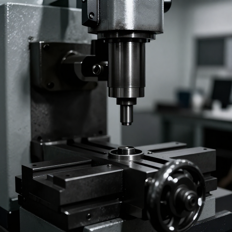


Jig Borer
Instruções
Build two square slideways
Build two square slideways
Two axes, and their squareness to each other is the machine's accuracy.
- Build a base 350 × 350 mm from 18 mm ply with aluminium angle ways for the X axis.
- Build a cross slide on top for the Y axis, its ways at 90 degrees to the first.
- Fix both with M5 × 30 socket head cap screws × 12, M5 flat washers × 24 and M5 hex nuts × 12.
- Set the squareness by the reversal method and confirm it twice.
Out-of-square axes make a distinctive error. Positions along either axis alone stay correct, but any hole needing both coordinates lands off by an amount proportional to how far out you are and how far along both axes you have travelled. So it passes a simple test and fails a real part — which is why squareness is checked by reversal rather than assumed.
This is the same reversal test used on the angle plate in batch 69. That blueprint made it a technique; here it is the machine's acceptance test.Materiais para este passo:
 Contraplacado de bétula báltica1 folha
 Cantoneira de alumínio2 peças
 Anilha plana24 peças
 Porca sextavada12 peças
Ferramentas necessárias:
 Serra tico-tico
 Berbequim sem fios
 Jogo de brocas
 Jogo de chaves Allen
 Esquadro combinado
 Paquímetro digital de 6 polegadas
Measure position with gauge blocks, not with a dial
Measure position with gauge blocks, not with a dial
The historically correct method, and the reason the machine could exist.
- Fit a fixed stop at one end of each axis and a movable stop on each slide.
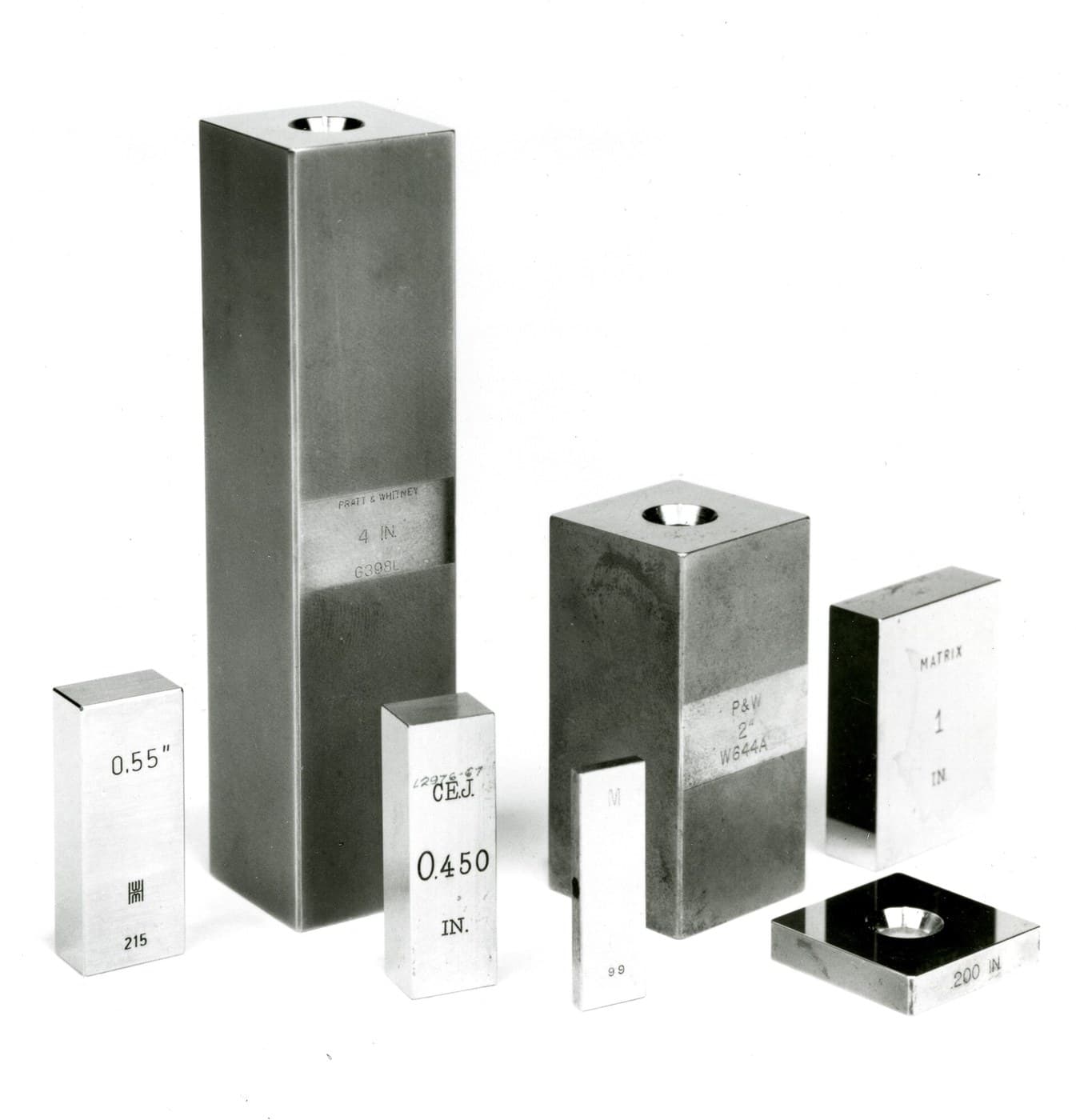
- Set a distance by placing a stack of gauge blocks between the two stops.
- Wind the slide until it just closes on the stack, then lock it.
- Remove the blocks and bore.
- For the next hole, change the stack by the required increment.
This is why the jig borer follows gauge blocks and not the other way round. Johansson's blocks made length available to a workshop to a fraction of a micron. A leadscrew has pitch error, wear and backlash; a stack of blocks has none of those, so setting position against blocks transfers the standard's accuracy directly into the machine. The earliest jig borers were built exactly this way.
Wring the blocks properly — slide them together under light pressure until they adhere. A stack that is merely stacked has films of air and oil between the faces, and each joint adds error.Materiais para este passo:
 Barra chata de alumínio1 peça
 Parafuso sem cabeça de ponta côncava4 peças
Ferramentas necessárias:
Paquímetro digital de 6 polegadasJogo de chaves Allen Jogo de limasBerbequim sem fios
Build the boring head
Build the boring head
A single-point tool on an adjustable radius, so one head bores any diameter.
- Mount a vertical spindle in two 608 bearings, with a Morse-taper socket or a plain 16 mm bore.
- Make a boring head: a block carrying a tool bit that can slide radially, adjusted by a screw.
- Lock the slide with two M5 cup point set screws.
- Fit a scale so the radial offset can be set and repeated.
Boring rather than drilling, for a specific reason. A drill follows its own point and will wander into a pre-existing dimple or a hard spot, so its position is only as good as the centre punch. A single-point boring tool cuts on one side and follows the SPINDLE'S axis, not the hole's — so it corrects position rather than inheriting it. That is why the machine is a jig BORER and not a jig driller.
Drill a smaller pilot first, then bore. The drill removes the bulk quickly and inaccurately; the boring head then puts the hole exactly where it belongs.Materiais para este passo:
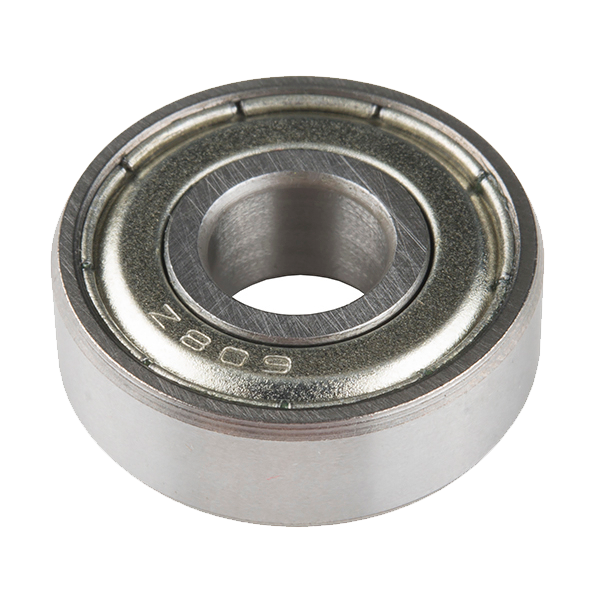 Ball Bearing - Non-Flanged (8mm Bore, 22mm OD)2 peças
 Varão redondo de alumínio1 peçaParafuso sem cabeça de ponta côncava2 peçasContraplacado de bétula báltica1 folha
Ferramentas necessárias:
Berbequim sem fiosJogo de brocasJogo de limas Torno de bancadaJogo de chaves AllenPaquímetro digital de 6 polegadas
Bore a hole pattern and measure position, not size
Bore a hole pattern and measure position, not size
The acceptance test for a positioning machine is a pattern, checked between centres.
- Set out a pattern of four holes on a 100 mm square.
- Bore all four, setting each coordinate with gauge blocks.
- Measure the centre distances of all four sides and both diagonals.
- Compare against the nominal 100 mm and 141.42 mm.
- Now mark out and drill the same pattern by hand and measure it the same way.
Materiais para este passo:
 Chapa de alumínio1 peça
Ferramentas necessárias:
Paquímetro digital de 6 polegadasEsquadro combinado Punção de centroBerbequim sem fios
Where the chain ends up, and history
Where the chain ends up, and history
The jig borer was developed in Switzerland in the 1910s — SIP and Dixi are the names associated with it — for the watch and instrument industries, where hole position in a movement plate decides whether a mechanism works at all. It spread to toolmaking, where jigs and fixtures need holes located far more accurately than the parts they will produce.
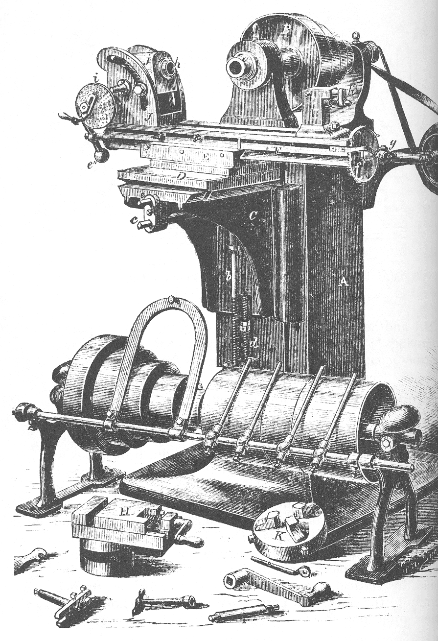
It closes the loop this batch opened. The 1817 planer needed a hand-scraped flat to be built at all. Each machine after it was built using the surfaces and accuracy of the ones before, and produced better ones in turn. The jig borer is the point at which that ratchet reaches instrument accuracy: a machine tool built to metrological standards, capable of making the jigs that make ordinary parts accurate. Machine tools stopped being tools that cut and became instruments that measure while cutting.
Why it needed the metrology first. Gauge blocks, the dividing head, the sine bar and the surface plate all had to exist before a machine could be built to this standard, because you cannot manufacture an accuracy you cannot measure. That ordering is not incidental — it is why the metrology batch had to come before this one, and why measurement generally precedes manufacture in every era.
What replaced it: CNC machining centres with ballscrews and linear scales do the same job with the same coordinate logic, and the numerical control that makes them possible is the direct descendant of dialling in coordinates by hand. The jig borer taught manufacturing to think in coordinates, and everything since has been a refinement of that habit.
Materiais
9- Referência
- 2 peçasReferência
- 24 peçasReferência
- 12 peçasReferência
- 1 peçaReferência
- Referência
- Ball Bearing - Non-Flanged (8mm Bore, 22mm OD)10% de comissão2 peçasR$6.27
- Referência
- 1 peçaReferência
Ferramentas necessárias
9- 1 vendor sell this, none ship to you yetReferência
- 1 vendor sell this, none ship to you yetReferência
- Referência
- Referência
- Referência
- Referência
- Referência
- Referência
- Referência
Blueprints relacionados
Estes blueprints compartilham conhecimento — técnicas, materiais ou princípios


CC0 Domínio Público
Este blueprint é liberado sob CC0. Você é livre para copiar, modificar, distribuir e usar este trabalho para qualquer finalidade, sem pedir permissão.
Apoie o Maker comprando produtos através do Blueprint, onde ele ganha uma Comissão Maker definida pelos vendedores, ou crie uma nova versão deste Blueprint e inclua-o como conexão no seu próprio Blueprint para compartilhar receita.